High-accuracy vibrating wire pressure sensor

A pressure sensor, high-accuracy technology, applied in the direction of elastic deformation meter fluid pressure measurement, etc., can solve the problems of high liquid surface pressure, easy interference of signal, complex deformation of flat film, etc., to improve the sealing effect and facilitate coating Glue seal, low hysteresis effect

Active Publication Date: 2011-02-09
邓铁六 +2
View PDF0 Cites 0 Cited by
  • Summary
  • Abstract
  • Description
  • Claims
  • Application Information

AI Technical Summary

Problems solved by technology

But present vibrating wire type pressure sensor has following deficiency: 1, the small boss at the center of the original deformable membrane is designed for connecting the string column, because the diameter is very small (be generally below 30% of the deformable membrane diameter), only play a role The function of connecting the chord column, so the deformable membrane can be regarded as a flat membrane with two parallel sides when working. When the liquid pressure is applied, the deformation of the flat membrane is complicated and the central part is deformed greatly, so the accuracy is low.
2. The height of the thread section at one end of the deformable membrane is extremely small, and there are only a few threads, so it is difficult to seal with the hydraulic joint and the liquid plane pressure is high, and the high-pressure liquid is easy to enter the thread gap to generate lateral swelling force, which seriously affects the accuracy.
However, the resistance strain type pressure sensor is not suitable for a humid environment (it has too high requirements for insulation), and has poor long-term stability and short life. Type pressure transmitter (pressure sensor plus current loop output circuit) solves these problems, but the price is too expensive

Method used


Image

  • High-accuracy vibrating wire pressure sensor
  • High-accuracy vibrating wire pressure sensor
  • High-accuracy vibrating wire pressure sensor

Examples


Embodiment 2

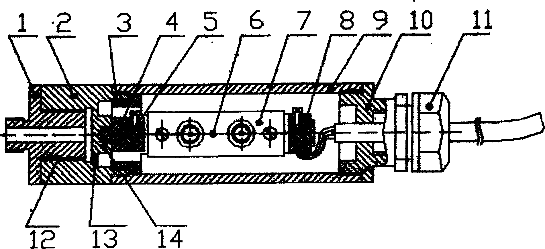
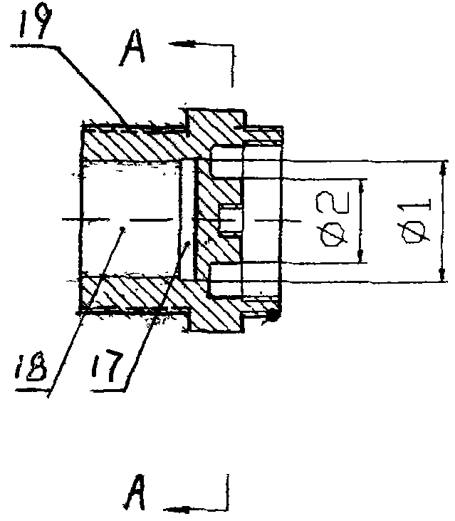
[0028] Embodiment 2, the structure of embodiment 2 is basically the same as embodiment 1, the difference lies in the connection structure between the extension section and the hydraulic joint. It is processed with an external thread on the extension of the working membrane body 2, and is connected with a hydraulic joint with an internal thread through the external thread. For the specific structure, see Figure 4 . From Figure 4 It can be seen that a blind hole 18 and a tool undercut 17 are processed on the extended section of the working membrane, and an external thread 19 is processed on the peripheral surface of the extended section. For detailed structure see figure 1 , which will not be described in detail here.

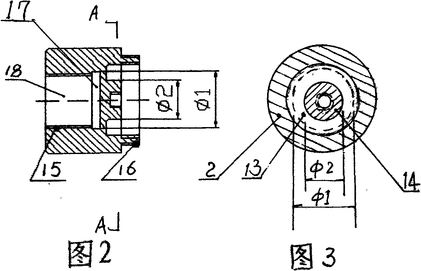
[0029] From figure 2 and image 3 The structure of the annular working membrane can also be seen in , where φ 1 is the outer diameter of the deformable film (the outer diameter of the undercut), φ 2 is the inner diameter of the deformable membrane (tha...


PUM


Abstract

The invention discloses a high-accuracy vibrating wire pressure sensor which mainly changes the diameter of a boss of a deformable film of the existing working film to 60%-90% of the diameter of the deformable film. The working film body has an extension section towards the direction of a hydraulic joint, and blind holes reaching the deformable film are processed on the extension section; female threads are processed on the walls of the blind holes or male threads are processed on the circumference surface of the extension section, and the threaded connection of the hydraulic joint and the extension section is realized by the female threads or the male threads; sealant is coated at the connections of the threads. Due to the fact that the diameter of the boss of the deformable film is 60%-90% of the diameter of the deformable film, and the threaded connection segment of the hydraulic joint and the working film is extended, the height of the threaded connection segment can be largely increased, and thus, thread track number is increased, which facilitates sealant coating and sealing. The sealing function is improved, and the impact of the liquid transverse expansive force on accuracy is eliminated.

Description

technical field [0001] The invention belongs to a liquid pressure sensor. Background technique [0002] The structure of the current vibrating wire pressure sensor is as follows: Figure 5 As shown, one end of the sensor housing 9 is equipped with a working membrane. The structure of the working membrane is that a circular groove is machined at one end of a cylinder, and a small boss 14 is formed in the middle to form the working membrane body 2, the body 2 The bottom of the working membrane is used as a deformable membrane 13, and external threads are processed on the circumferential surface at both ends of the body 2. One end of the deformable membrane is connected to the hydraulic joint 1 through the external thread, and the other end of the working membrane is connected to the sensor housing 9 through the external thread. String frame 3, string column 4, steel string 6, magnetic head plate 7, string clamp 5 and string clamp 8 are installed, the other end of sensor housin...

Claims


Application Information

Patent Timeline
Patent Type & Authority Patents(China)
IPC IPC(8): G01L7/08
Inventor 邓铁六赵胜利赵振远
Owner 邓铁六
Why Eureka
Try Eureka