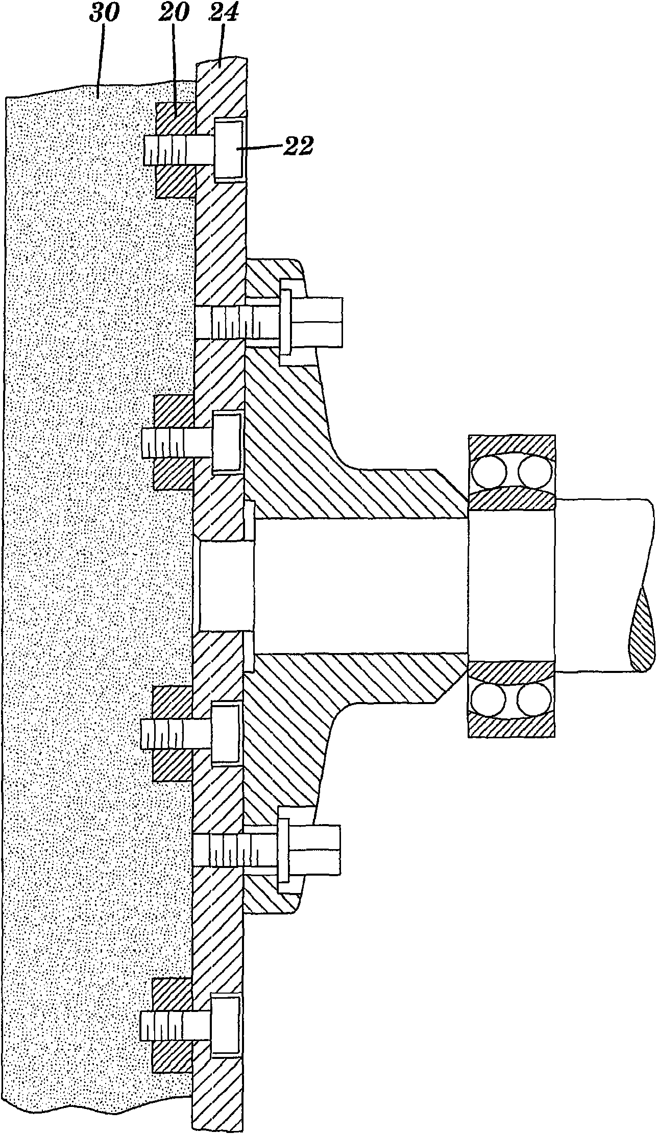
Disc grinding wheel with integrated mounting plate
A technology for mounting plates and grinding wheels, applied in abrasives, grinding devices, bonded grinding wheels, etc., to solve problems such as additional weight and cost constraints
- Summary
- Abstract
- Description
- Claims
- Application Information
AI Technical Summary
Problems solved by technology
Method used
Image
Examples
example 1
[0050] Glass-reinforced polyester coupons (Type 5300 and 5600 plate molding compounds from Zehrco Plastics, Inc., Ashtabula OH, USA) were fabricated into rods with a cross-section of 1 / 2 inch by 1 / 2 inches (nominal 12mm x 12mm), and were evaluated before and after firing at approximately 160°C for 10 hours to evaluate thermal stability and mechanical properties.
[0051] The mechanical strength is tested by measuring the yield strength of a sample of the material before and after firing. use 4204 (Instron Corporation, Canton, Massachusetts) electromechanical test system, to test the yield strength, the system is equipped with a span of 2 inches (5cm) Three-point bending fixture and a free-moving roller running at a feed rate of 0.5 inches (1.3 cm) per minute. As shown in Table II below, the material was found to substantially exceed the required strength of 40 megapascals (MPa), while also exceeding the optional strength of 100 MPa.
[0052] Table II
[0053] ...
example 2
[0078] Two-component glass-reinforced polyester specimens (Premi- 1203-30, 30% glass-filled polyester, Premix, Inc., North Kingsville Ohio) is processed into rods with a cross-section of 1 / 2 inch by 1 / 2 inch (nominal 12mm by 12mm), And yield strength and tensile strength were tested essentially as described in Example 1.
[0079] As shown in Table VI below, both compositions were found to substantially exceed the required minimum and optional yield strengths of 40 and 100 MPa, respectively.
[0080] Table VI
[0081] component 1
component 2
Yield stress (MPa)
Yield stress (MPa)
average
264.9
212.7
standard deviation
42.8
30.2
[0082] As shown in Table VII below, the tensile strength of the material was well in excess of the required minimum of 500 lbs (2224 Newtons).
[0083] Table VII
[0084]
[0085] Mounting panels 40 having a 5 inch outside diameter were fabricated substantially as desc...
example 3
[0089] Glass-reinforced polyester specimens produced by Polyply Composition, Inc. of Grand Haven MI were processed into rods with a cross-section of 1 / 2 inch by 1 / 2 inch (nominal 12 mm by 12 mm) and rolled in Yield and tensile strengths were tested essentially as described in Example 1 before and after firing to about 160°C.
[0090] The test results shown in Tables IX-XI below indicate that these specimens met the required minimum yield strength of 40 megapascals (MPa) and the required minimum tensile strength of 500 lbs (2224 Newtons). The fired specimens failed to meet the optional optional yield strength level of 100 MPa.
[0091] Table IX - Before Roasting
[0092] Great#
Yield stress (MPa)
1
173.9
2
220.5
3
163.7
average
186
standard deviation
30.3
[0093] Table X-76 After Roasting
[0094] Great#
Yield stress (MPa)
1
60.3
2
92.5
...
PUM
 Abstract
Description
Claims
Application Information
 - R&D Engineer
- R&D Manager
- IP Professional
- Industry Leading Data Capabilities
- Powerful AI technology
- Patent DNA Extraction
Browse by: Latest US Patents, China's latest patents, Technical Efficacy Thesaurus, Application Domain, Technology Topic, Popular Technical Reports.
© 2024 PatSnap. All rights reserved.Legal|Privacy policy|Modern Slavery Act Transparency Statement|Sitemap|About US| Contact US: help@patsnap.com


