
Multi-frequency band self-excited interference elimination repeater

A technology of interference elimination and self-excitation elimination, applied in electrical components, wireless communications, radio relay systems, etc., can solve problems such as base station control channel blocking, repeater system self-excited oscillation, and difficulty in engineering applications. Small input quantity, reduced isolation requirements, and the effect of eliminating interference

Inactive Publication Date: 2009-11-18
深圳市信特科技有限公司
View PDF0 Cites 23 Cited by
  • Summary
  • Abstract
  • Description
  • Claims
  • Application Information

AI Technical Summary

Problems solved by technology

[0004] In practical engineering applications, due to the limitation of the installation conditions of the donor antenna and the coverage antenna, the isolation between the donor antenna and the coverage antenna is not high. If the repeater system gain is greater than the isolation between the donor antenna and the coverage antenna, it will lead to Self-excited oscillation, causing the blockage of the control channel of the base station, and even causing the paralysis of the base station system
In the same-frequency wireless repeater system application, it is usually required that the gain of the repeater system is 10-15dB lower than the isolation between the donor antenna and the coverage antenna, resulting in low gain of the repeater system and limited coverage area
In order to improve the repeater system gain and expand the wireless coverage capability of the repeater system, it is necessary to improve the isolation between the donor antenna and the coverage antenna, which is usually difficult to achieve in engineering applications

Method used


Image

  • Multi-frequency band self-excited interference elimination repeater
  • Multi-frequency band self-excited interference elimination repeater
  • Multi-frequency band self-excited interference elimination repeater

Examples


Embodiment Construction

[0026] The present invention will be described in further detail below in conjunction with the accompanying drawings and embodiments. The specific implementation examples described here are only used to explain the present invention, not to limit the present invention.

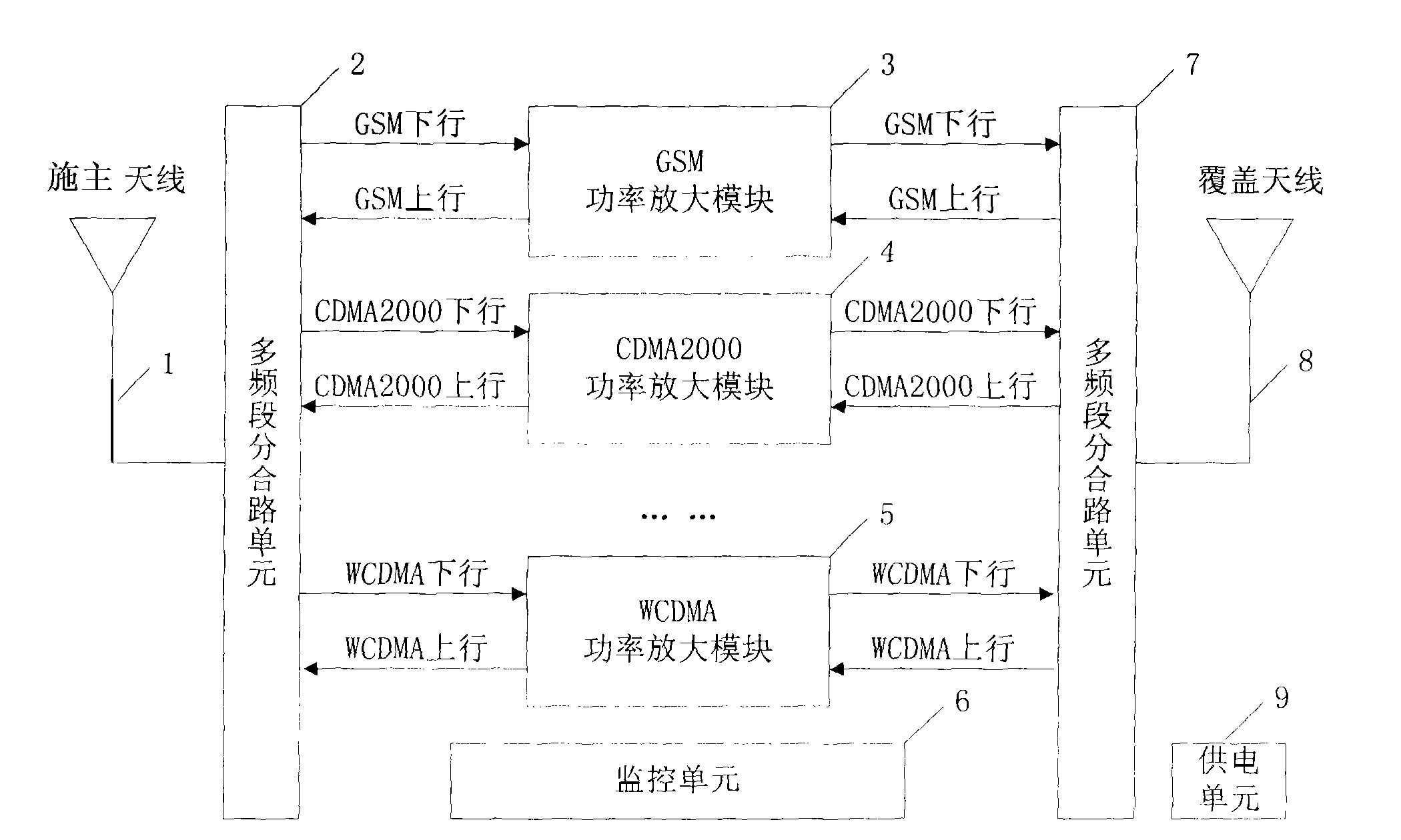
[0027] figure 1 Among them, the donor antenna 1 couples downlink signals from various base stations operating in different communication systems and frequency bands from the air. These downlink signals may include GSM frequency bands, CDMA frequency bands, CDMA2000 frequency bands, WCDMA frequency bands, etc. These downlink signals are respectively outputted by the multi-band splitting and combining unit 2 as downlink signals of different frequency bands. These downlink signals are respectively filtered and amplified by different power amplifier modules 3, 4, 5, etc., and then passed through the multi-band splitting and combining unit. 7 Combine the processed downlink signals of multiple frequency bands, and ...


PUM


Abstract

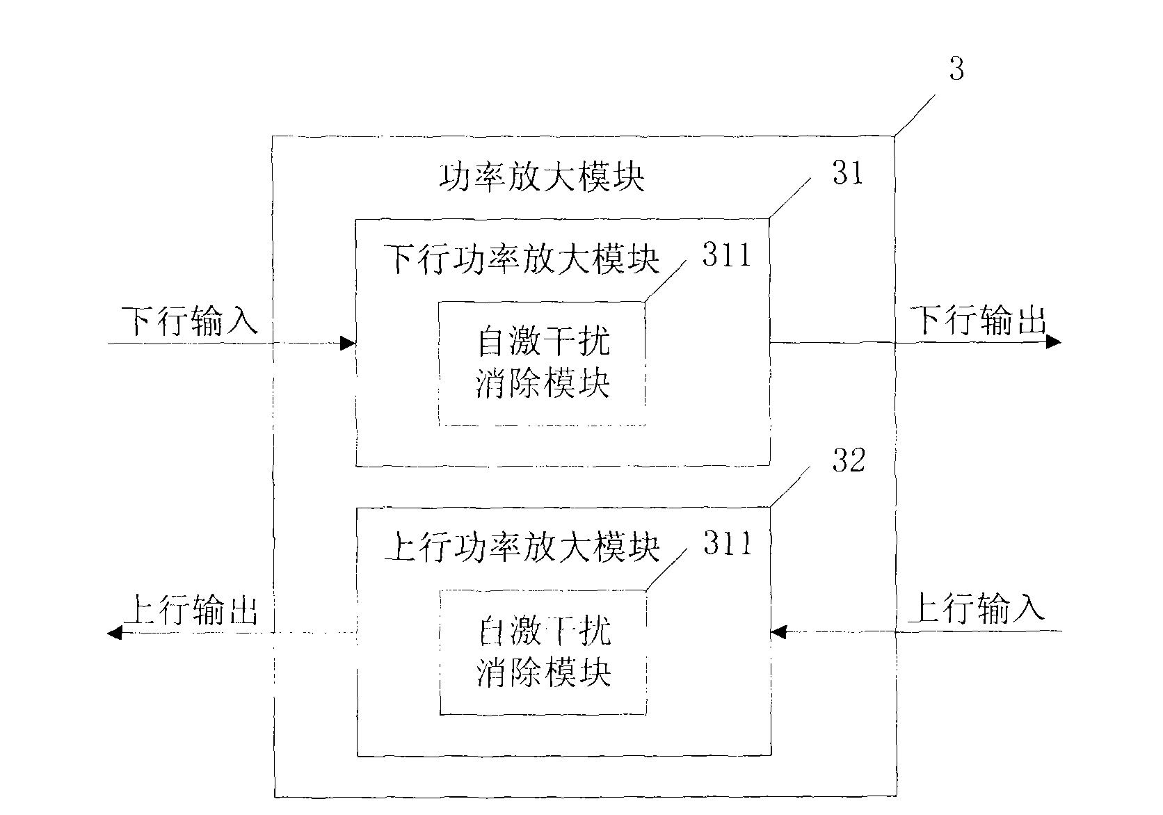
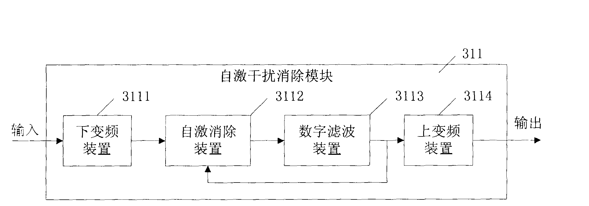
The invention is applicable to the communication field and can carry out relay amplification on a wireless communication system with various frequency bands and simultaneously eliminate self-excited interference of signals. The repeater comprises a downlink which is composed of a multi-frequency band branching / combining unit, a downlink power amplification module and multi-frequency band branching / combining units which are sequentially connected, and an uplink which is composed of a multi-frequency band branching / combining unit, an uplink power amplification module and multi-frequency band branching / combining units which are sequentially connected. The repeater system can process wireless signals with multiple frequency bands, thereby being capable of containing a plurality of downlinks and a plurality of uplinks. The downlink power amplification module and the uplink power amplification module in the embodiment of the invention are both provided with self-excited interference elimination modules, thereby being capable of eliminating the self-excited interference of the repeater. The multi-frequency band self-excited interference elimination repeater can reduce the number of equipments which are used for the repeater and installed by mobile communication operators and increase the wireless coverage range.

Description

technical field [0001] The invention relates to the field of mobile communication, in particular to a multi-band self-excited interference elimination repeater. Background technique [0002] Currently, there are different communication systems and frequency bands in commercial mobile communication systems, such as GSM, CDMA, CDMA2000, WCDMA, etc., and most mobile communication operators operate wireless communication services in multiple frequency bands at the same time. At present, the widely used repeater system can only perform wireless relay processing on one wireless frequency band. For the wireless coverage of the same area, multiple sets of different repeater systems are required, resulting in high cost of wireless coverage and complicated construction. If there is a repeater that can perform wireless relay processing on multiple wireless frequency bands, the number of repeater equipment installed by mobile communication operators can be reduced, and the wireless cove...

Claims


Application Information

Patent Timeline
IPC IPC(8): H04W88/08H04B7/14
Inventor 方超
Owner 深圳市信特科技有限公司
Learn More