
Multifunctional laser holography stamping process

A laser holography and molding technology, applied in printing, printing presses, decorative arts, etc., can solve the problems of adverse effects of laser pattern printing process, inconsistent molding products, and high plate wheel, avoiding the phenomenon of smearing, improving the quality of printing pressure, The best laser effect

Inactive Publication Date: 2009-11-18
SHANGHAI FORWARD MASCH CO LTD
View PDF0 Cites 8 Cited by
  • Summary
  • Abstract
  • Description
  • Claims
  • Application Information

AI Technical Summary

Problems solved by technology

Before the molding process starts, the metal molded plate with pre-etched laser holographic pattern must be rolled on the cylindrical plate wheel, but after the roll is completed, there will inevitably be molded plate seams, so the traditional molding machine is used to produce The laser holographic molded film products that come out will form a plate seam due to the existence of the molded plate seam, which will have an adverse effect on the subsequent laser pattern printing process
If you want to avoid the seam in the printing process, you need special expensive equipment. If you do not deal with the seam problem in the printing process, there will be a 10% to 20% printed waste rate.
In addition, because the traditional laser holographic molding machine adopts the one-time embossing process of a single plate wheel, the temperature of the plate wheel is required to be relatively high. Generally, it is required to reach about 200°C, so that the laser pattern information of the metal mold plate can be saturated, thoroughly and clearly The plastic film can be easily stretched and formed (the softening temperature of the plastic film is around 165°C), which will easily cause inconsistencies in the molded products of each version, and even cause paste.

Method used


Image

  • Multifunctional laser holography stamping process

Examples


Embodiment Construction

[0012] Below in conjunction with embodiment and accompanying drawing, the present invention will be further described:

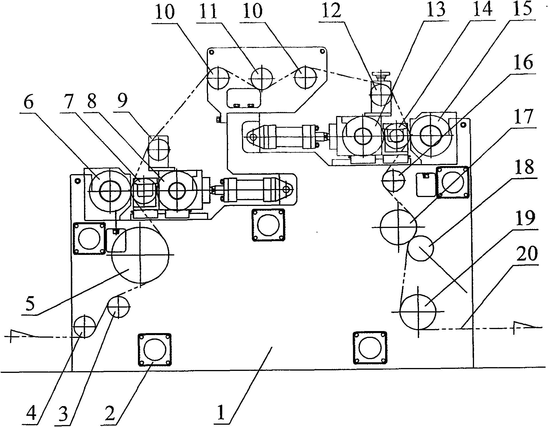
[0013] This embodiment is a laser holographic embossing machine for embossing patterns on RVC films. The embossing group has a structure of two embossing stations. The position of the slit on the plate wheel is monitored by the photoelectric eye. The adjustment of the PLC control circuit of the motor makes the plate seams staggered during the molding of the two stations to improve the quality of the printing. The structure of this embodiment is as shown in the drawings, including frame 1, beam 2, tensioning wheel 3, guide wheel a 4, preheating wheel 5, first molding station, tension control group, second molding station, Guide wheel bb16, ironing wheel 17, rubber pressure wheel 18, cooling wheel 19, printing film 20, photoelectric eye and PLC control circuit, the installation sequence is: the left and right frame 1 is supported by 5 middle beams 2, and the p...


PUM


Abstract

The invention discloses a multifunctional laser holography stamping process. The traditional laser holography compression press uses the process of single-version roller one-step embossing, which has adverse impact on subsequent laser pattern pressing due to the existing version gap. The invention mainly use a stander, a beam, a tension pulley, a stator a, a pre-heating wheel, a first stamping station, a tension-control group, a second stamping station, a stator bb, an ironing wheel, a rubber clamping wheel, a cooling wheel, a printing film, a photoelectric eye and a PLC control circuit. The invention has the beneficial effects that due to utilization of two-station stamping process, plastic film can go through laser holography embossing twice, stagger the version gap and can not be blurred; lowering the temperature requirement on wheel surface of the wheel is favor of stamped pictures and texts of the film to be more plump and saturated; more intensive optical effect is generated to achieve better laser effect; the quality of laser holography stamping on the plastic film is improved greatly.

Description

technical field [0001] The invention relates to a surface treatment (imprinting) technology of plastic products, in particular to a laser holographic embossing process on plastics. Background technique [0002] The traditional laser holographic embossing machine adopts single-plate roller one-time embossing technology. It only sets a set of molding stations between the unwinding group and the coiling group. Due to the limitation of its structure, there is only one printing method. The molding station includes a plate wheel, a liner wheel, and a pressure wheel. Press to the lining wheel, and finally the lining wheel and the pressure wheel press together to the plate wheel along the direction of the guide rail. The moving push-pull mechanism is connected to the fixed seat at both ends of the pressure wheel. The push-pull mechanism generally adopts the hydraulic type. Before the molding process starts, the metal molded plate with pre-etched laser holographic pattern must be ro...

Claims


Application Information

Patent Timeline
Patent Type & Authority Applications(China)
IPC IPC(8): B41F19/02B44C5/00
Inventor 林培辉
Owner SHANGHAI FORWARD MASCH CO LTD
Learn More