
Electric connector terminal

An electrical connector and terminal technology, applied in the field of electrical connector terminals, can solve the problems of non-conformity with electronic products, short electrical conduction path, large space, etc., and achieve the effect of shortening the electrical conduction path

Inactive Publication Date: 2011-04-13
FOXCONN (KUNSHAN) COMPUTER CONNECTOR CO LTD +1
View PDF2 Cites 0 Cited by
  • Summary
  • Abstract
  • Description
  • Claims
  • Application Information

AI Technical Summary

Problems solved by technology

The first conductive terminal and the second conductive terminal can be in direct contact and are electrically connected. The first and second conductive terminals form a compressible contact under the action of the elastic component. Therefore, the electrical conduction path is relatively short.
However, the stress of the electrical connector terminals connecting the chip module and the circuit board is mainly concentrated in the area where the upper and lower ends are in contact with the chip module and the circuit board. Since the elastic component is a hollow, helical spring, the electrical connection The low-stress area of ​​the device terminal occupies a large space, which does not meet the needs of the increasingly miniaturized development of electronic products

Method used


Image

  • Electric connector terminal
  • Electric connector terminal
  • Electric connector terminal

Examples


Embodiment Construction

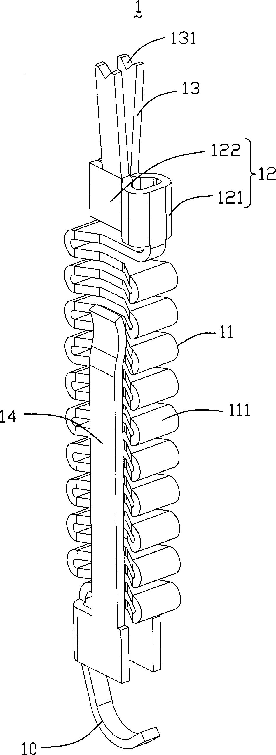
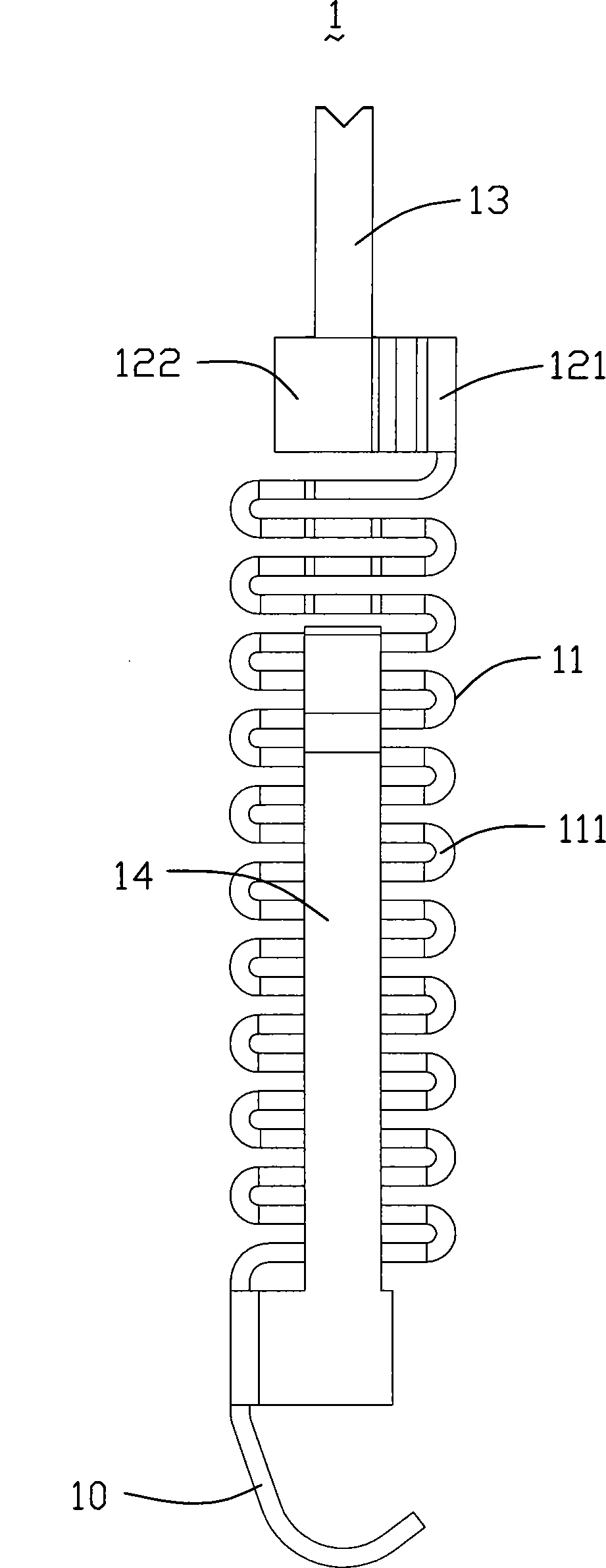
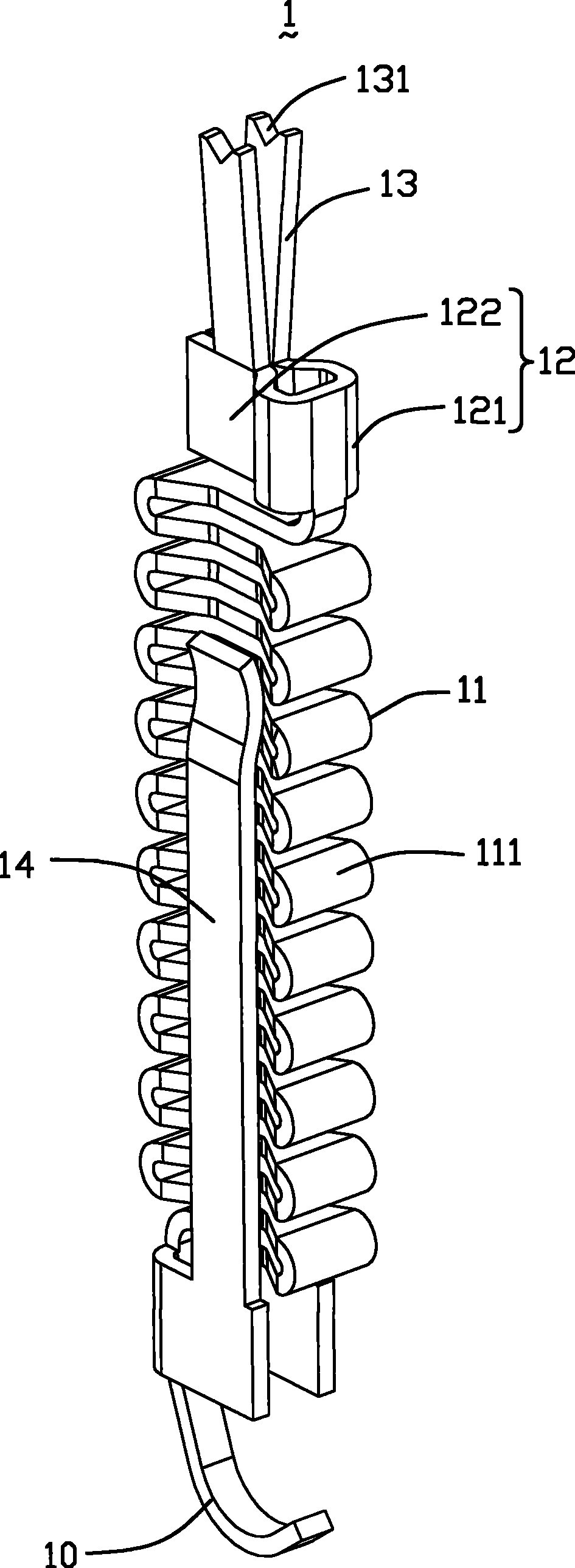
[0011] Below, will combine figure 1 and figure 2 The specific implementation manner of the electrical connector terminal 1 of the present invention is introduced. The electrical connector terminal 1 of the present invention includes a hook-shaped first contact portion 10, an elastic arm 11 extending vertically upward from one end of the first contact portion 10 in the same plane through several times of bending, and continuing upward from one end of the elastic arm 11. An extended support arm 12 and a pair of second contact portions 13 connected to the support arm 12 . The elastic arm 11 is bent each time to form a folding unit 111 , and each folding unit 111 has a shape with thick sides and a thin middle. The support arm 12 includes an arc-shaped support arm 121 connected to the elastic arm 11 and a flat plate-shaped support arm 122 parallel to the free end of the arc-shaped support arm 121 . The second contact portion 13 protrudes above the flat support arm 122 . The fr...


PUM


Abstract

The invention discloses an electric connector terminal, which comprises a first contact part, a second contact part, an elastic arm, a support arm and at least one arm, wherein the elastic arm is formed by bending for multiple times, one end of the elastic arm is connected with the first contact part, and the support arm is connected with the other end of the elastic arm and a second contact part.The arm is formed by the convex extension of the first contact part laterally towards the direction of the second contact part, the tail end of the arm is positioned at the position close to the support arm, and the arm is butted to the support arm when the electric connector terminal is in a using state. The electric connector terminal reduces the electric conduction path by the arm at the side,reduces the impedance, and simultaneously reduces the space occupied by a low stress area of the electric connector terminal.

Description

【Technical field】 [0001] The invention relates to an electrical connector terminal, in particular to an electrical connector terminal capable of shortening an electrical conduction path and reducing impedance. 【Background technique】 [0002] Electrical connectors are widely used in the electronic field to electrically connect the chip module to the circuit board to realize the transmission of signals and data between the chip module and the circuit board. According to the shape and structure of the conductive components of the chip module, electrical connectors can generally be divided into pin grid array (Pin Grid Array, PGA) connectors, ball grid array (Ball Grid Array, BGA) connectors and planar grid Grid Array (Land Grid Array, LGA) connector. Correspondingly, the conductive terminals accommodated in the electrical connector are also classified into PGA type terminals, BGA type terminals and LGA type terminals. [0003] U.S. Patent No. 6,561,817 discloses an electrical...

Claims


Application Information

Patent Timeline
Patent Type & Authority Patents(China)
IPC IPC(8): H01R12/00H01R13/24H01R43/16H01R12/55
Inventor 陈铭佑萧世伟
Owner FOXCONN (KUNSHAN) COMPUTER CONNECTOR CO LTD
Learn More