
Method for using outdoor air to cool room devices

A technology of outdoor air and indoor devices, applied in application, refrigerators, heating methods, etc., can solve problems such as difficult adjustments

Inactive Publication Date: 2009-11-11
FLKT WOODS AB
View PDF4 Cites 6 Cited by
  • Summary
  • Abstract
  • Description
  • Claims
  • Application Information

AI Technical Summary

Problems solved by technology

Since cooling and ventilation are usually from different suppliers, it is not easy to adapt these additional structures into usable equipment

Method used


Image

  • Method for using outdoor air to cool room devices

Examples


Embodiment Construction

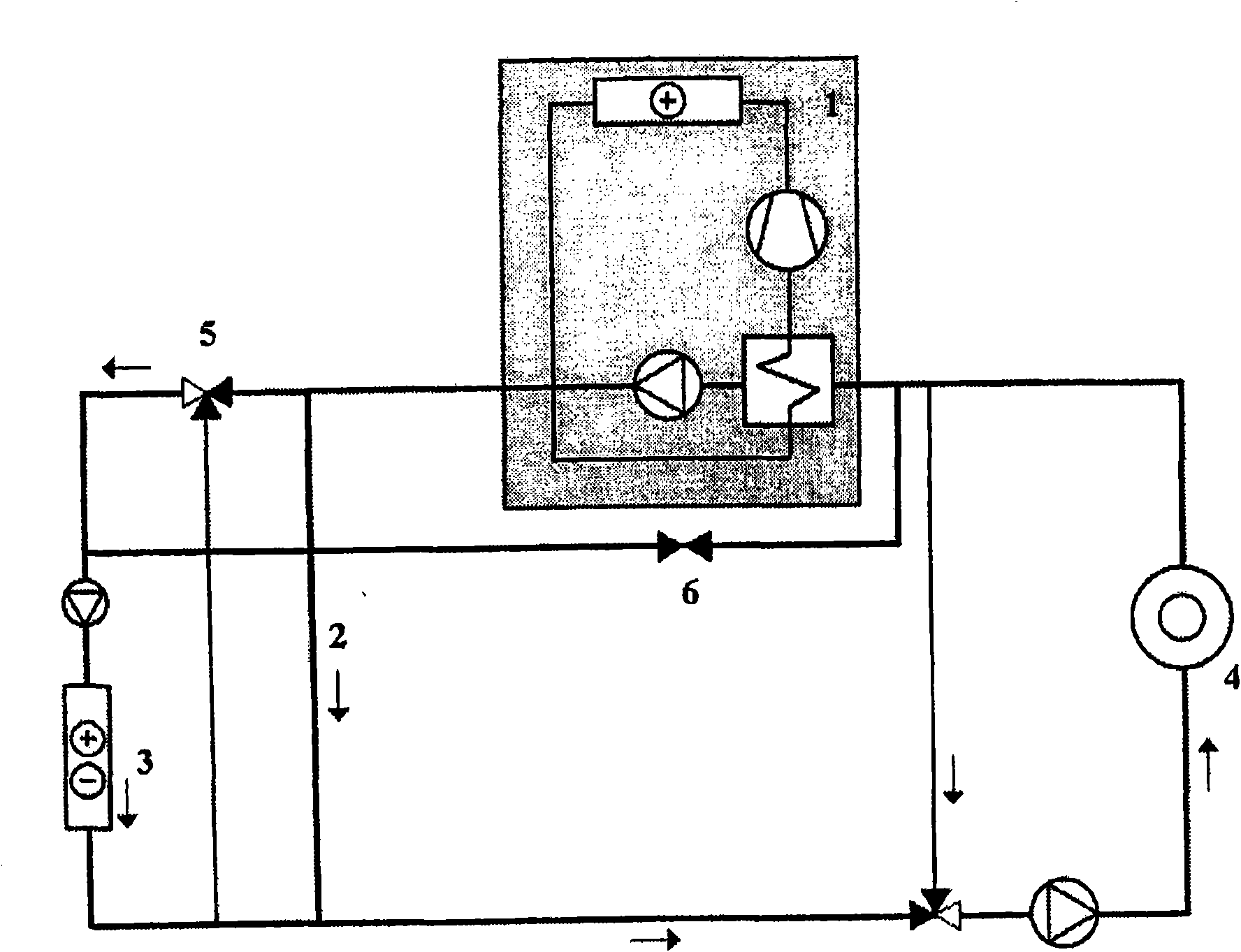
[0011] In the schematic diagram shown in the figures, the main circulation loop is designated by the reference number 2 . The outside air enters via the cooling radiator / heating radiator 3 also called supply air radiator. Return water from all or part of the indoor installations, eg all or part of the chilled beams 4 , is directed to the circulation circuit of the radiator 3 . This water heats the air passing through the cooling radiator / heating radiator 3 to the appropriate temperature for blowing into the room. At the same time, as the water imparts energy to the air, it cools itself. The cooled water is directed back to cool the indoor unit. This transfers the free cooling energy contained in the outdoor air to the indoor unit.

[0012] When not enough cooling energy is obtained from the outside air, the cooling compressor 1 can be used at the same time to provide additional power. The water returning from the indoor unit is partly diverted to the branch 6 which handles...


PUM


Abstract

The invention discloses a method for using outdoor air to cool room devices, e.g. chilled beams (4). The invention is implemented such that the water returning from the room devices is used in the supply air radiator (3) to heat the supply air, in which case this water cools and is conducted back to the room devices to cool the room spaces.

Description

technical field [0001] The present invention relates to a method of cooling indoor units, such as cooled beams, with outdoor air. Background technique [0002] Cooling needs typically arise in interior spaces of buildings when the temperature of the outdoor air is high. Internal loads in indoor spaces, such as lighting and computers, also create cooling needs when the temperature of the outside air is low, eg below 5°C. In this case, it is possible to take advantage of the lower temperature of the outdoor air to cool the indoor air. Usually only the lower temperature of the outdoor air is utilized in the fan air blowing indoors, that is, blowing low-temperature air inside, for example, air at 15°C. However, this cooling power is not sufficient, but it would be advantageous if the cooling energy contained in the outside air could also be conducted to the indoor unit. [0003] Therefore, cooling indoor units with outside air is not typically used in ventilation cooling beca...

Claims


Application Information

Patent Timeline
Patent Type & Authority Applications(China)
IPC IPC(8): F24F5/00
CPCF24F5/0003F24F5/001F24F2011/0006F24F3/06F24F11/0001F25B25/005F24F5/00F24F12/00
Inventor P·马基南
Owner FLKT WOODS AB
Learn More