Air conditioning with recovery wheel, dehumidification wheel, cooling coil, and secondary direct-expansion circuit

a direct expansion circuit and air conditioning technology, applied in lighting and heating apparatus, ventilation systems, heating types, etc., can solve the problems of limiting the amount of cooling that can be provided, reducing the cooling effect of the cooling coil, and consuming energy

Pending Publication Date: 2022-07-21
SEMCO INC
View PDF0 Cites 0 Cited by
  • Summary
  • Abstract
  • Description
  • Claims
  • Application Information

AI Technical Summary

Benefits of technology

The patent provides a new system for cooling buildings using chilled beams. The system has several advantages over previous designs, including better cooling performance, compatibility with chilled beams, reduced risk of condensation, and improved energy efficiency. The system also includes multiple pump modules with sensors, control valves, and a digital controller to optimize cooling water delivery and prevent condensation. Overall, the system provides a more effective and economical solution for cooling buildings.

Problems solved by technology

But adding or removing heat or humidity (moisture) typically involves the expenditure of energy.
Further still, in chilled beam applications, humidity levels in the room air can limit the amount of cooling that can be provided through the chilled beams because the chilled beams cannot be cooled below the room air dew point or else condensation will occur on the chilled beams which will drip on the occupants and other contents of the space.
In chilled water systems, however, the minimum temperature that the air leaving the cooling coil can reach has been limited by how cold the chilled water can be produced using traditional chiller performance limitations.
As a result, the amount of humidity that can be removed from the outdoor air, for example, is limited.
Moreover, in prior art systems, when supply air was cooled in the cooling coil sufficiently to provide the desired level of supply air humidity, supply air temperatures were often colder than desired.

Method used


Image

  • Air conditioning with recovery wheel, dehumidification wheel, cooling coil, and secondary direct-expansion circuit
  • Air conditioning with recovery wheel, dehumidification wheel, cooling coil, and secondary direct-expansion circuit
  • Air conditioning with recovery wheel, dehumidification wheel, cooling coil, and secondary direct-expansion circuit

Examples


Embodiment Construction

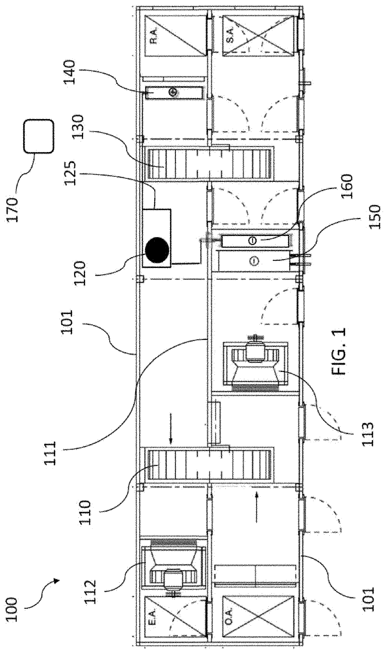
[0008]This invention provides, among other things, various air conditioning units, systems, and methods that control temperature and humidity, for instance, within a space (e.g., in a building). Various units and systems, for example, include a recovery wheel, a (e.g., passive) dehumidification wheel, a primary cooling coil, a secondary system evaporator coil, and a secondary system condensing coil. Further, in various embodiments, a supply airstream passes outdoor air first through the recovery wheel, then through the primary cooling coil, then through the dehumidification wheel, and then to the space. Still further, in many embodiments, an exhaust airstream passes return air from the space through the dehumidification wheel, and then through the recovery wheel. Further still, in particular embodiments, the supply airstream passes outdoor air first through the recovery wheel, then through the primary cooling coil, then through the secondary system evaporator coil, then through the ...


PUM


Abstract

Systems and methods for controlling temperature and humidity within a space in a building. Outdoor air and return air from the space are passed through particular equipment in a particular order. Equipment includes a secondary direct-expansion refrigeration circuit, a recovery wheel, a primary cooling coil, secondary circuit evaporator and condenser coils, and a dehumidification wheel. Various embodiments include multiple zones, chilled beams, and a dedicated outdoor air supply (DOAS) subsystem delivering dehumidified air to active chilled beams. In various embodiments, supply air passes first through the recovery wheel, then through the primary cooling coil, then through the dehumidification wheel, and then to the space. Further, in some embodiments, exhaust air passes through the dehumidification wheel and then through the recovery wheel. Pump modules may supply chilled beams and control their temperature to avoid condensation. A chiller may supply cooling water to both the primary cooling coil and the pump modules.

Description

RELATED PATENT APPLICATIONS[0001]This United States patent application is a continuation-in-part (CIP) patent application of, and claims priority to, U.S. patent application Ser. No. 16 / 712,052, filed Dec. 12, 2019, titled: AIR CONDITIONING WITH RECOVERY WHEEL, DEHUMIDIFICATION WHEEL, AND COOLING COIL, which is: a non-provisional patent application of, and claims priority to, U.S. Provisional patent application Ser. No. 62 / 779,356, filed Dec. 13, 2018, titled: AIR CONDITIONING IMPROVEMENTS; and (Ser. No. 16 / 712,05) is also a continuation-in-part (CIP) patent application of, and claims priority to, U.S. patent application Ser. No. 15 / 616,702, filed Jun. 7, 2017, issued Jun. 23, 2020 as U.S. Pat. No. 10 / 690,358, titled: AIR CONDITIONING WITH RECOVERY WHEEL, PASSIVE DEHUMIDIFICATION WHEEL, COOLING COIL, AND SECONDARY DIRECT-EXPANSION CIRCUIT, which is a non-provisional patent application of, and claims priority to U.S. Provisional patent application Ser. No. 62 / 347,517, filed Jun. 8, 2...

Claims


Application Information

Patent Timeline
IPC IPC(8): F24F11/30F24F3/14F24F5/00F24F12/00F25B5/04F25B49/02
CPCF24F11/30F24F3/1423F24F3/1429F24F5/0046F24F12/003F24F2011/0002F25B5/04F25B49/02F24F2003/1464F24F2005/0057F24F12/006F24F2203/1032F24F2203/104F25B2400/06F25B2600/0253Y02B10/40Y02B30/52Y02B30/70F24F2013/221
Inventor FISCHER, JOHN C.
Owner SEMCO INC
Why Eureka
Try Eureka