
Active chilled beam tail end device and active chilled beam air conditioning system

A terminal device, active technology, applied in air conditioning system, heating method, pipeline arrangement, etc., can solve the problem of easy to wet indoor floor, wet users, etc., to achieve the effect of convenient operation, easy maintenance and improved sealing

Pending Publication Date: 2020-03-17
GREE ELECTRIC APPLIANCES INC
View PDF0 Cites 0 Cited by
  • Summary
  • Abstract
  • Description
  • Claims
  • Application Information

AI Technical Summary

Problems solved by technology

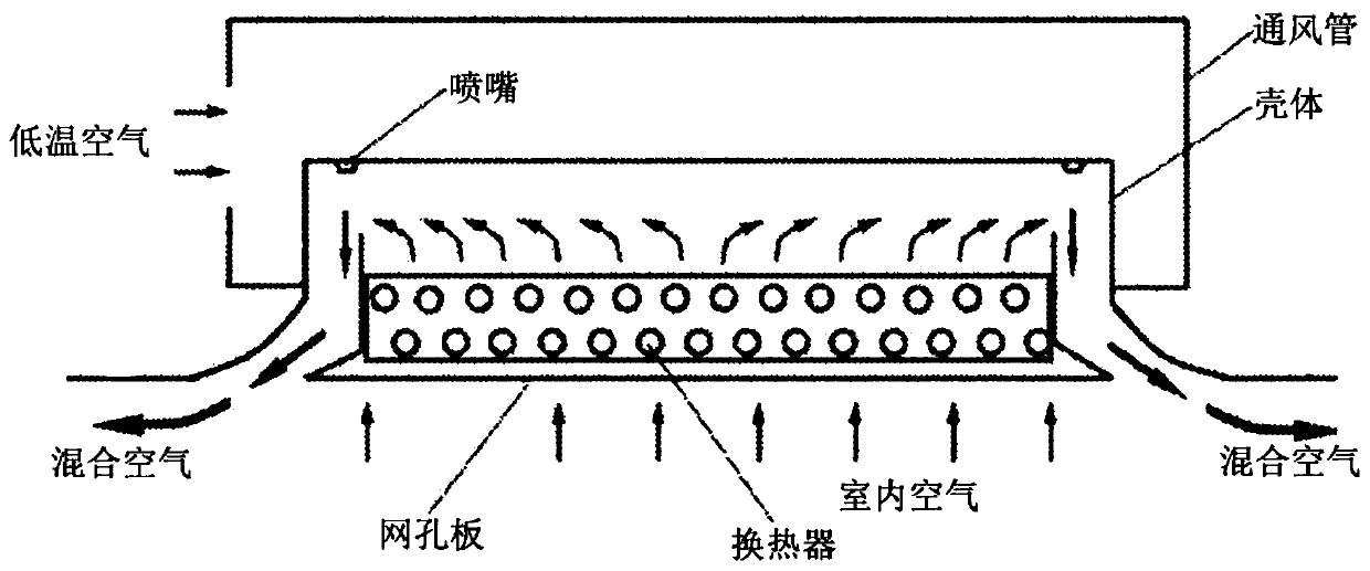
[0004] In the above process, when the indoor air with high temperature is in contact with the heat exchanger and the nozzle, condensation may occur on the surface of the heat exchanger and the surface of the nozzle, and the condensation water will gather and fall, and it is easy to wet the indoor floor. , and even wet the user

Method used


Image

  • Active chilled beam tail end device and active chilled beam air conditioning system
  • Active chilled beam tail end device and active chilled beam air conditioning system
  • Active chilled beam tail end device and active chilled beam air conditioning system

Examples


Embodiment 1

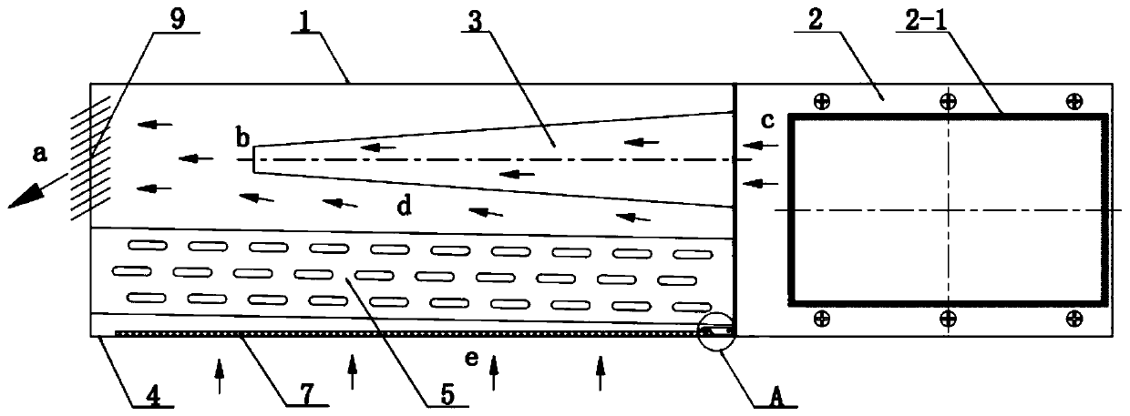
[0032] An active chilled beam end device such as Figure 2-3 As shown, it includes a casing 1, a ventilation pipe 2, a nozzle 3, a mesh plate 4, a heat exchanger 5, a water tray 6, and a filter 7.

[0033] The right end of the housing 1 is provided with an air inlet hole, the left end of the housing 1 is provided with an air outlet hole, the lower end of the housing 1 is provided with a mesh plate installation hole, and the right end of the housing 1 is connected with the ventilation pipe 2 by the fastener. The side walls are fixed together. In the first embodiment, the fasteners are bolts or screws.

[0034] In order to guide the flow direction of the wind, the air outlet of the casing 1 is provided with a plurality of wind deflectors 9 arranged side by side.

[0035] A hinge shaft is provided on the side of the wind deflector 9 close to the housing 1, and the housing 1 is provided with a hinge hole for interference fit with the hinge shaft. With such setting, the user can ...

Embodiment 2

[0049] An active chilled beam air conditioning system, comprising an active chilled beam end device, the active chilled beam end device being the active chilled beam end device. The active chilled beam end device can prevent the condensed water from falling, collect the condensed water, make full use of the cooling capacity of the condensed water, improve the cooling efficiency, and improve the user experience.


PUM


Abstract

The invention discloses an active chilled beam tail end device and an active chilled beam air conditioning system. The tail end device comprises a shell, a vent pipe, a nozzle, a mesh plate, a heat exchanger, a water pan and a filter, wherein one end with an air inlet hole of the shell is connected with the side wall of the vent pipe; the lower end face of the shell is provided with a mesh plate mounting hole for mounting the mesh plate; the nozzle which is in communication with the inner cavity of the vent pipe is arranged at the air inlet of the shell; one end, close to the vent pipe, of theheat exchanger is lower than one end, far away from the vent pipe, of the heat exchanger; both the water pan and the filter are arranged on the upper end face of the mesh plate; and the water pan isconnected with the filter through a siphon device. The active chilled beam air conditioning system comprises an active chilled beam tail end device, wherein the active chilled beam tail end device isthe active chilled beam tail end device disclosed by the invention. Through the adoption of the active chilled beam tail end device, the ground or a user can be protected from getting wet by falling condensed water gathered on the surface of the heat exchanger and the surface of the nozzle; the cooling capacity of the condensed water is fully utilized; the refrigerating efficiency is improved; andthe user experience is improved.

Description

technical field [0001] The invention relates to the technical field of air conditioning equipment, in particular to an active chilled beam terminal device and an active chilled beam air conditioning system. Background technique [0002] The active chilled beam air conditioning system is an air conditioning system integrating cooling and heating, which can provide a good indoor climate environment. The active chilled beam end device in the active chilled beam air conditioning system is as follows figure 1 As shown, it includes ventilation pipes, nozzles, heat exchangers and mesh plates located in the shell. [0003] When cooling, the cooled low-temperature air will be ejected from the nozzle when it flows through the ventilation pipe. According to the Venturi effect: when the high-speed airflow passes through the barrier, a negative pressure will be formed near the port above the leeward side of the barrier, thereby Adsorption occurs, so the indoor air located under the mes...

Claims


Application Information

Patent Timeline
Patent Type & Authority Applications(China)
IPC IPC(8): F24F1/0011F24F1/0063F24F1/0073F24F13/06F24F13/22
CPCF24F1/0011F24F1/0063F24F1/0073F24F13/06F24F13/222
Inventor 黄玉优王子平谢文利
Owner GREE ELECTRIC APPLIANCES INC
Learn More