
An induction heating cooking device

A technology of induction heating and cooker, which is applied in the direction of induction heating, induction heating control, induction heating device, etc., can solve the problems of affecting the accuracy of temperature measurement, the decline of the mechanical strength of the top plate, and the inconvenient use of the cooker, so as to reduce infrared radiation and stabilize The effect of ambient temperature

Inactive Publication Date: 2009-10-21
HITACHI APPLIANCES INC
View PDF4 Cites 2 Cited by
  • Summary
  • Abstract
  • Description
  • Claims
  • Application Information

AI Technical Summary

Problems solved by technology

[0010] In the above-mentioned prior art, the method shown in Patent Document 1 has a time delay because the temperature of the pot is detected through the top plate, so there is an error between the actual temperature of the pot and the temperature detected by the thermistor, and it cannot be highly accurate. The problem of accurately detecting the temperature of the pot
[0011] In addition, in the method shown in Patent Document 2, in order to use the infrared sensor to detect the infrared radiant energy from the pot without being absorbed by the top plate, a hole is opened on the top plate, and a material that easily transmits infrared rays is embedded in the hole, so the mechanism of the top plate decrease in strength
[0012] Moreover, if there are steps or gaps on the surface of the top plate, there is a problem that it is difficult to clean the surface.
[0013] In addition, the infrared sensor of the system described in Patent Document 3 has a structure that is easily affected by the heat generated by the heating coil and the temperature rise of the top plate, so there is a problem that the temperature of the pan cannot be detected with high accuracy.
[0014] Furthermore, since the surrounding temperature of the infrared sensor tends to rise, the heating is frequently stopped to protect the infrared sensor, so it is inconvenient to use as a cooker.
[0015] Also, in the method described in Patent Document 4, the band-pass filter of 0.8 to 4 μm provided on the light-receiving surface of the infrared sensor is limited in the materials that can be used for the filter, making it an expensive component.
[0016] Furthermore, if a Peltier element is used for cooling the infrared sensor, the structure becomes complicated and the price becomes high
Moreover, if a fan is used to cool the infrared sensor, the ambient temperature of the infrared sensor will change due to the sway of the fan's wind, so fluctuations will occur in the output signal of the infrared sensor, which will affect the measurement accuracy of the temperature.

Method used


Image

  • An induction heating cooking device
  • An induction heating cooking device
  • An induction heating cooking device

Examples


Embodiment 1

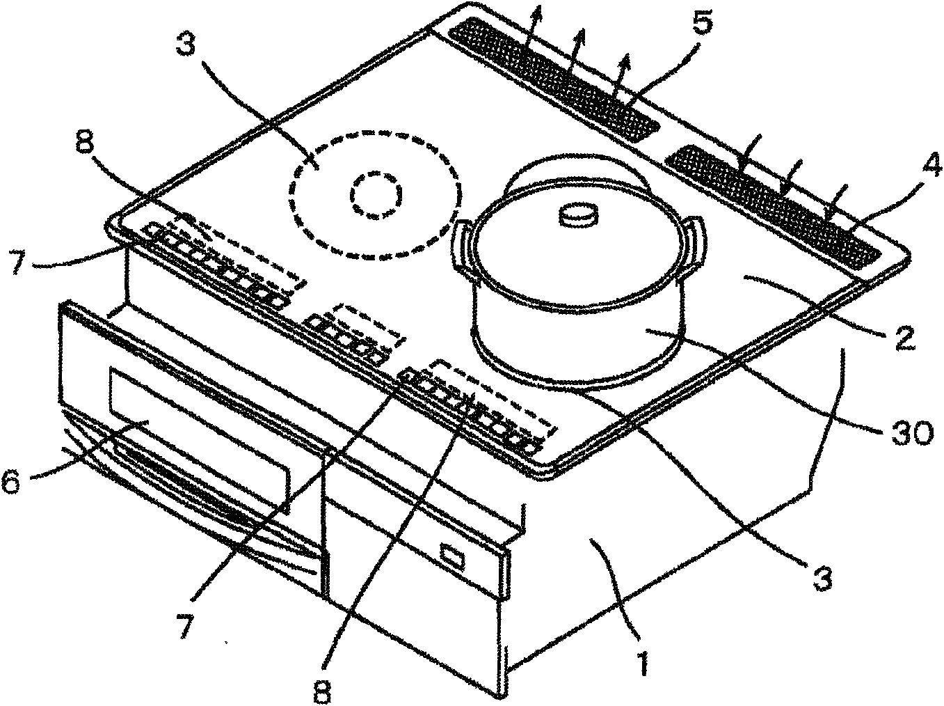
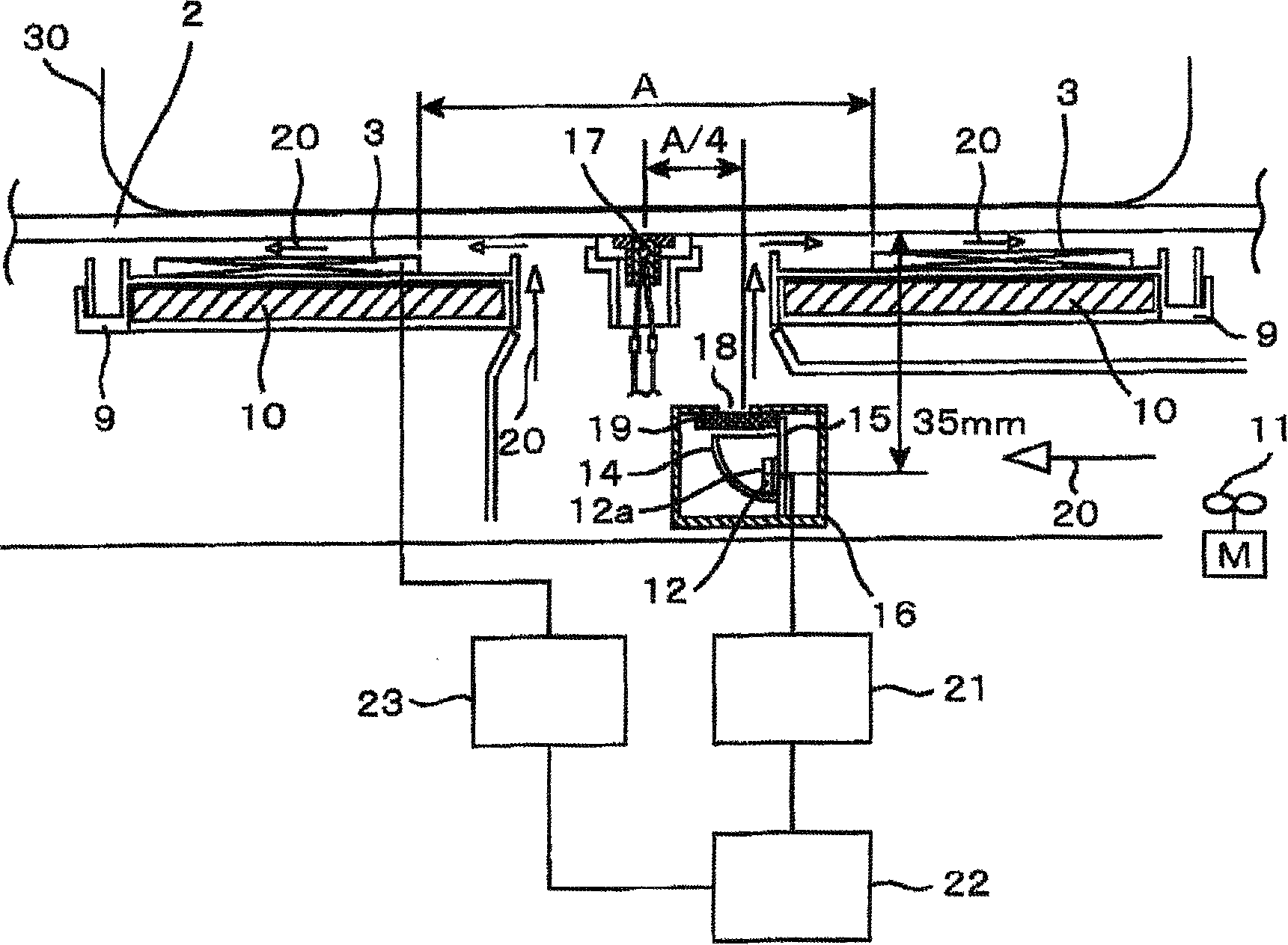
[0039] figure 1 is an external perspective view of the induction heating cooker in the first embodiment, figure 2 and image 3 is a longitudinal sectional view of main parts of the induction heating cooker in the first embodiment, Figure 4 is a graph representing the spectral radiation intensity curve of a blackbody, Figure 5 It is a graph showing the transmittance curve of crystal glass.

[0040] exist figure 1 Among them, the top plate 2 is horizontally arranged on the upper surface of the main body 1 of the induction heating cooker.

[0041] The top plate 2 is made of highly heat-resistant crystal glass, and an object to be heated, such as a pan 30 made of a magnetic material such as iron or a non-magnetic material such as aluminum, is placed.

[0042] Heating coils 3 are arranged on the left and right in the upper part of the main body 1 below the top plate 2 . An object to be heated such as a pan 30 placed on the top plate 2 is induction heated.

[0043] On the ...

Embodiment 2

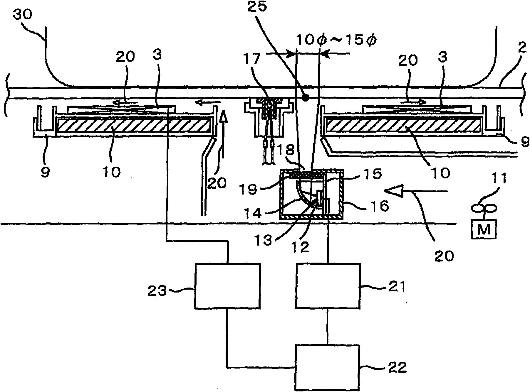
[0086] Image 6 It is a longitudinal sectional view of main parts showing a second embodiment of the present invention.

[0087] exist Image 6 In , the same parts as those in the above-mentioned first embodiment are assigned the same symbols, and description thereof will be omitted.

[0088] In this embodiment, a wall 24 made of resin or the like having a small heat capacity and poor thermal conductivity is provided between the shield case 16 and the infrared sensor 12 .

[0089]As described above, by arranging the infrared sensor 12 in the space covered by the wall 24, even if the temperature of the shield case 16 occurs due to the influence of the leakage magnetic flux from the heating coil 3 or the influence of the temperature rise of the top plate 2 and the heating coil 3 Changes, the influence of temperature is also difficult to transfer to the infrared sensor 12,. Therefore, high-precision temperature detection can be performed.

[0090] In addition, by covering the...


PUM


Abstract

The invention provides an induction heating cooking device with a simple structure which can precisely detect the temperature of a pot arranged on a top plate and control the power supplied to a heating coil. The induction heating cooking device is provided with a heating coil (3) for heating objects, a top plate (2) above the heating coil (3) for placing the heated objects, an infrared sensor (12) below the heating coil (3) for detecting the infrared rays radiated by the heated objects, a sensitive surface (12a) covering the infrared sensor (12), an insulation plate (19) with infrared permeation characteristics, a temperature enumeration unit (21) for calculating the temperature of the heated object based on the output of the infrared sensor (12), and a control unit (22) for controlling the power supplied to the heating coil (3) based on the output of the temperature enumeration unit (21). The control unit (22) detects the temperature of the heated object and controls the temperature of the heating coil (3) based on the output of the infrared sensor (12) and sets the attenuation region of the infrared rays of the insulation plate to be a wavelength region with waves of longer than 4 mu m.

Description

technical field [0001] The present invention relates to an induction heating cooker that detects the temperature of an object to be heated placed on a top plate and controls power supplied to a heating coil. Background technique [0002] In such a conventional induction heating cooker, there is a method in which the temperature of an object to be heated such as a pan is detected by a thermistor on a top plate, and the temperature of the object to be heated is controlled (for example, refer to Patent Document 1). [0003] In addition, there is also a method in which an infrared ray transparent material is provided on a part of the top plate, an infrared sensor is provided under the infrared ray transparent material, and the infrared ray radiated from the pot through the infrared ray transparent material is efficiently detected by the infrared sensor. , and detect the pot temperature with high precision (for example, refer to Patent Document 2). [0004] In addition, there is...

Claims


Application Information

Patent Timeline
Patent Type & Authority Applications(China)
IPC IPC(8): H05B6/12H05B6/06
CPCH05B2213/07H05B6/062
Inventor 川村光辉山田清司大友博
Owner HITACHI APPLIANCES INC
Learn More