
High temperature energy-saving tunnel kiln for physical thermal circulation application

A tunnel kiln and physical heat technology, which is applied in the field of high temperature energy-saving tunnel kiln for physical heat cycle utilization, can solve the problems of high energy consumption and insufficient utilization of thermal energy, and achieve the effect of expanding the application range.

Active Publication Date: 2009-10-14
岳阳市安达耐火材料有限公司
View PDF0 Cites 25 Cited by
  • Summary
  • Abstract
  • Description
  • Claims
  • Application Information

AI Technical Summary

Problems solved by technology

The main reason for high energy consumption is that heat energy is not fully utilized: high-temperature materials above 1400°C are cooled by a large amount of cold air through the cooling belt, and the physical heat is released into the furnace air, and a part of 450-600°C hot air is drawn out as combustion-supporting air. into the burner, part of it is sent to the drying room to dry the billet, and a large part of the hot air cannot be used and is directly discharged; the exhaust gas after combustion in the combustion chamber enters the preheating zone to heat the billet, part of the heat is absorbed by the billet, and part of the heat is Discharge with exhaust gas (250°C) into the exhaust system

Method used


Image

  • High temperature energy-saving tunnel kiln for physical thermal circulation application
  • High temperature energy-saving tunnel kiln for physical thermal circulation application
  • High temperature energy-saving tunnel kiln for physical thermal circulation application

Examples


Embodiment Construction

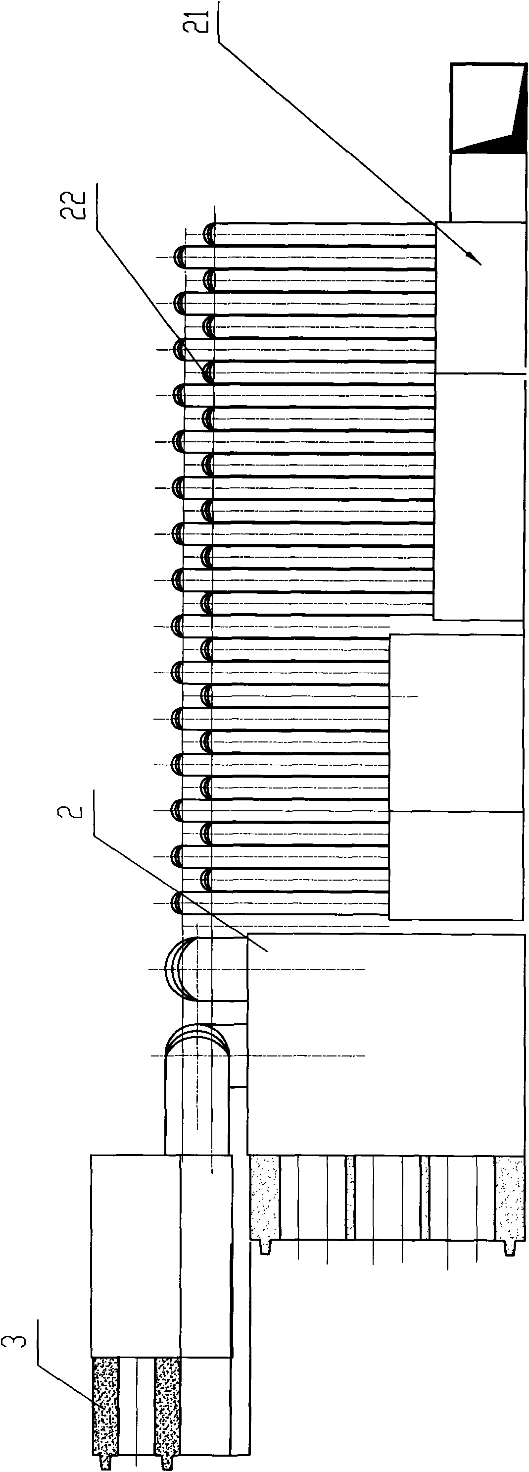
[0026] Depend on Figures 1 to 14 It can be seen that the present invention is composed of a preheating zone A, a firing zone B and a cooling zone C, and a billet drying room 8 and a billet drying room 9 are arranged on one side of the kiln body, and its features include:

[0027] A metal tubular air preheater 2 is installed in the furnace of the middle temperature section of the cooling zone C of the tunnel kiln, and a silicon carbide air preheater 3 made of non-metallic materials is installed in the furnace of the high temperature section of the cooling zone, wherein the metal tubular preheater 2 One end is connected to the fan 1, the other end is connected to the silicon carbide air preheater 3, the other end of the silicon carbide air preheater 3 is connected to the high temperature air duct 5, and then the high temperature air duct 5 passes the preheated combustion air through the high temperature air duct The air valve 6 is connected to the high temperature burner 7 .

...


PUM


Abstract

The invention relates to a high temperature energy-saving tunnel kiln for physical thermal circulation application. A metal tube type air preheater is arranged in a medium temperature section furnace cavity in a tunnel kiln cooling zone; a silicon carbide air preheater made from non-metallic material is arranged in a high temperature section furnace cavity in the tunnel kiln cooling zone; wherein, one end of the metal tube type air preheater is connected with a blower and the other end thereof is connected with the silicon carbide air preheater; the other end of the silicon carbide air preheater is connected with a high temperature airpipe; then preheated combustion-supporting air is connected to a high temperature combustor by a high temperature airpipe air valve through the high temperature airpipe air; a group of forced cooling blowers are arranged at the low temperature section of the cooling zone to blow wind to the high temperature zone and high temperature blowers are arranged at the medium temperature section of the cooling zone to pump hot air to a gas pipe mounting groove to heat coal gas, excess heat in the gas pipe mounting groove is connected to a blank drying room and a blank drying shed by a pipeline; wherein, the blower arranged at a preheating zone pumps excess heat and waste gas from the cooling zone and a burning zone, which enters the blank drying shed by the pipeline.

Description

technical field [0001] The invention relates to the design and manufacture industry of kiln equipment and the refractory material and ceramic production industry, and is suitable for the physical heat circulation utilization of high-temperature energy-saving tunnel kilns for medium and high-temperature firing kilns such as refractory material products and ceramic products. Background technique [0002] At present, the energy consumption of tunnel kilns using low calorific value producer gas in the refractory industry generally ranges from 1.82 million kcal / ton of product to 2.66 million kcal / ton of product, that is, the coal consumption per ton of product is 260-380 kg, and the comprehensive thermal efficiency is 30- About 40%. The main reason for high energy consumption is that heat energy is not fully utilized: high-temperature materials above 1400°C are cooled by a large amount of cold air through the cooling belt, and the physical heat is released into the furnace air, a...

Claims


Application Information

Patent Timeline
IPC IPC(8): F27B9/02F27B9/12F27B9/30F27D13/00F27D17/00F27D9/00F23L15/00
CPCY02E20/34
Inventor 周绍芳
Owner 岳阳市安达耐火材料有限公司
Learn More