Wear-resistant collecting vat of charging centrifugal machine

A pusher centrifuge and collection tank technology, which is applied in the field of collection systems, can solve the problems of material particle crushing and collection tank wear, and achieve the effect of reducing particle crushing and solving serious wear

Inactive Publication Date: 2009-10-07
ZHEJIANG QINGJI IND
View PDF0 Cites 2 Cited by
  • Summary
  • Abstract
  • Description
  • Claims
  • Application Information

AI Technical Summary

Problems solved by technology

[0004] The purpose of the present invention is to solve the problem that the solid material and the static collection tank are strongly collided due to the strong inertia of the centrifuge in the existing solid collection tank, which easily causes the material particles to be broken and causes serious wear to the collection tank. , to provide a collection tank lined with a layer of polymer material, which can reduce wear and reduce the broken solid particle wear-resistant collection tank of the pusher centrifuge

Method used


Image

  • Wear-resistant collecting vat of charging centrifugal machine
  • Wear-resistant collecting vat of charging centrifugal machine
  • Wear-resistant collecting vat of charging centrifugal machine

Examples


Embodiment Construction

[0019] The technical solutions of the present invention will be further specifically described below through the embodiments and in conjunction with the accompanying drawings.

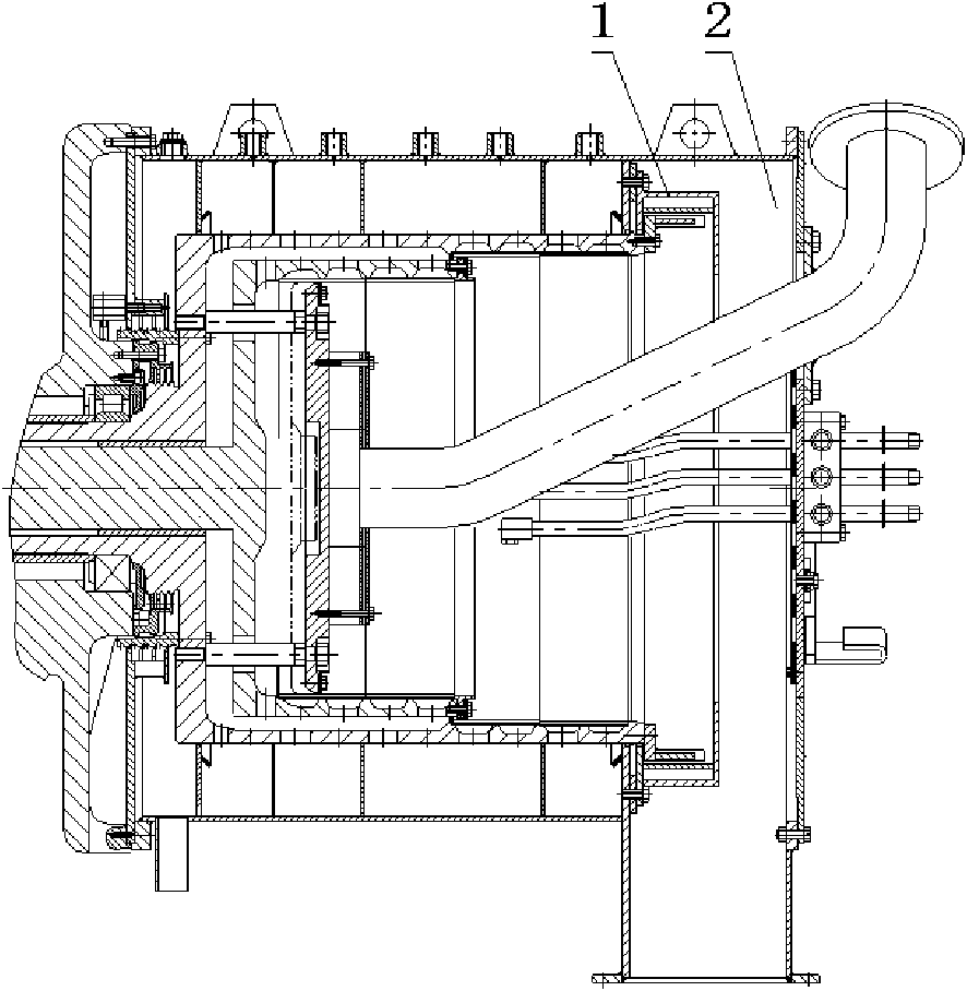
[0020] see figure 1 with figure 2 , the present embodiment comprises a pusher centrifuge collection system 2, a solid collection device 1, the solid collection device 1 is installed in the pusher centrifuge collection system 2, a U-shaped collection tank 4 is established in the solid collection device 1, and the collection A wear-resistant layer 3 is installed on the groove 4 lining.

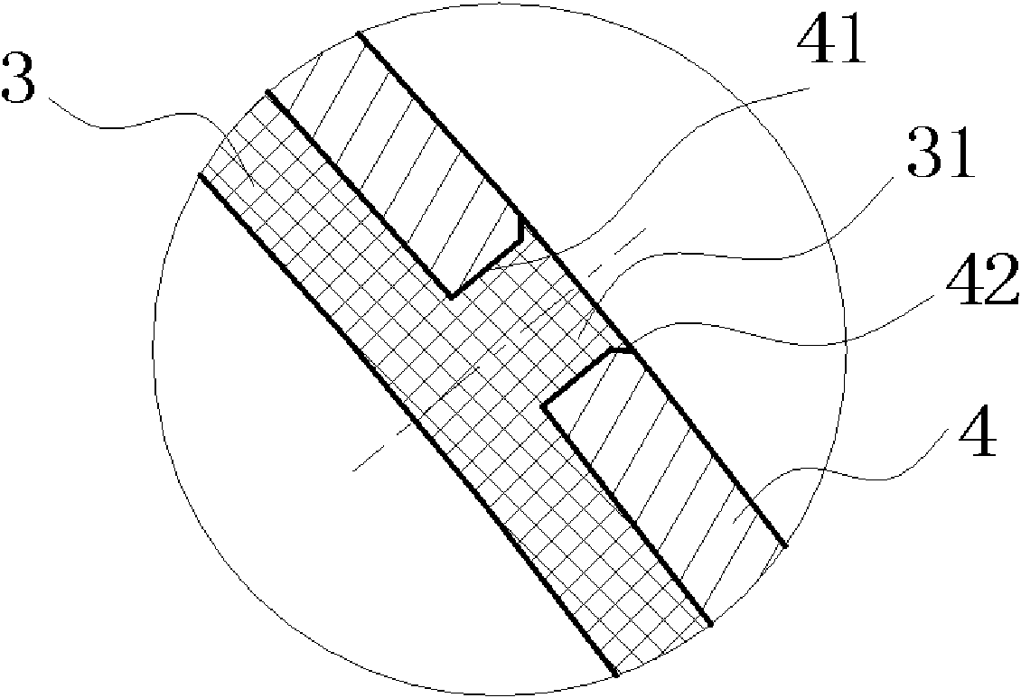
[0021] Such as image 3 , Figure 4 As shown, a number of circular small holes 41 are processed around the cylinder body of the collecting tank 4, and a protruding pin 31 corresponding to the small hole 41 is provided on the wear-resistant layer 3, and the hole end of each small hole 41 is provided with Chamfering 42, the end of lug 31 is flush with small hole 41, wear-resistant layer and cylinder body one-time inje...


PUM


Abstract

The invention relates to a collection system for charging centrifugal machine after severing materials, especially relates to a wear-resistant collecting vat of charging centrifugal machine improved from solid materials collecting vat of charging centrifugal machine, which includes charging centrifugal machine collection system and solid collection apparatus. The feature is indicated that the aforementioned solid collection apparatus is installed in the charging centrifugal machine collection system, there is a collecting vat with the intersecting surface as U type or semi-circle type or rectangle or special-shaped, and there is a wear layer lining in the collecting vat. The wear layer can absorb some kinetic energy carried by part of solid particles deviating from B grade barrate as the wear layer has definite elasticity, which can drives down the particle broken problem, furthermore can effectively account for the problem of abrasion of the solid collecting vat as the wear layer is nano type SY polyene and polyester.

Description

technical field [0001] The patent of the invention relates to a collection system for materials separated by a pusher centrifuge, in particular to an improved pusher centrifuge wear-resistant collection tank for the solid material collection tank of the pusher centrifuge. Background technique [0002] The pusher centrifuge is a continuous operation high-efficiency filter centrifuge. The suspension to be separated is continuously fed into the centrifuge through the feed pipe, accelerated by the feed distributor, and evenly sprinkled in the first-stage drum, and the solid part is trapped on the screen to form a ring-shaped filter cake. When the first-stage drum, which is both rotating and reciprocating, is on the return journey, this part of the filter cake is pushed forward for a certain distance along the axial direction of the drum. During the process, the subsequent material coming in from the sieve vacated by the filter cake forms a new filter cake. With the reciprocati...

Claims


Application Information

Patent Timeline
IPC IPC(8): B04B11/06
Inventor 陶渊卿沙恩典吴将天吕丽珍胡兴陶张浩
Owner ZHEJIANG QINGJI IND
Why Eureka
Try Eureka