Closed self-circulation hydraulic pipeline flusher

A technology of flushing device and hydraulic pipeline, which is applied in the directions of cleaning hollow objects, cleaning methods and utensils, chemical instruments and methods, etc. The effect of reducing the amount of oil used for circulating flushing, improving flushing efficiency, and easy implementation

Inactive Publication Date: 2009-09-30
CHINA FIRST METALLURGICAL GROUP
View PDF0 Cites 28 Cited by
  • Summary
  • Abstract
  • Description
  • Claims
  • Application Information

AI Technical Summary

Problems solved by technology

As a result, the circulating flushing pump station is huge, and the oil consumption increases as the fuel tank increases.
However, when it is used to flush a pipeline with a relatively small diameter, due to the influence of parameters such as pipe diameter, flow velocity, loss along the process, and the working pressure of the flushing pump, a large amount of oil is unloaded by the oil pump under pressure limit and directly overflows back to the oil tank, resulting in a high flushing efficiency. low
[0006] Therefore, it is necessary to improve the existing open oil circulation flushing method in order to solve technical problems such as excessive oil tank, large amount of flushing oil, and the need to increase the working pressure of the flushing pump to increase the flushing flow rate.

Method used


Image

  • Closed self-circulation hydraulic pipeline flusher
  • Closed self-circulation hydraulic pipeline flusher
  • Closed self-circulation hydraulic pipeline flusher

Examples


Embodiment Construction

[0021] The invention will be further described below in conjunction with the accompanying drawings with specific embodiments:

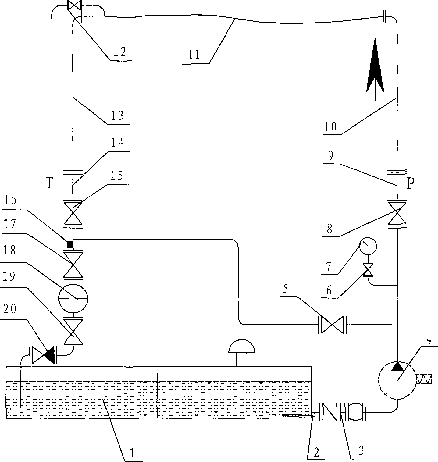
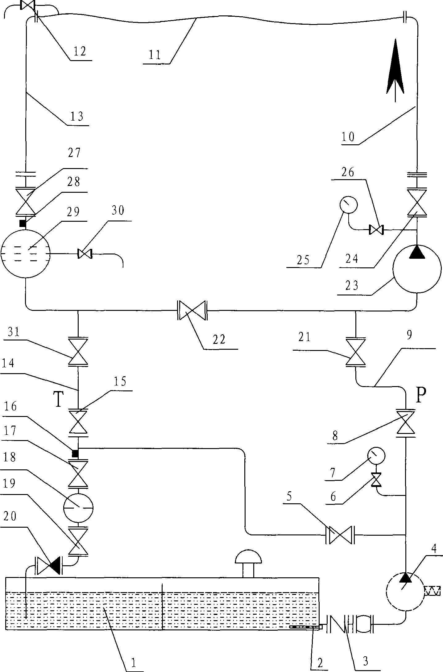
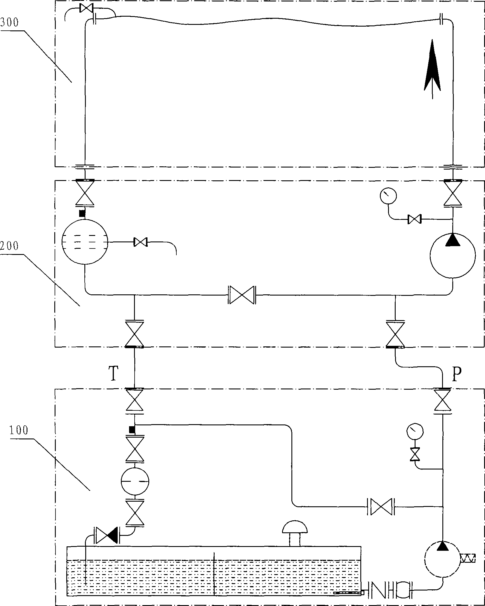
[0022] Because the oil in the traditional open oil circulation flushing system returns to the oil tank 1 through the oil return pipe, the oil flows in an open manner and is easy to contact with the atmosphere to generate a large number of air bubbles. To guarantee the normal operation of the oil pump 4, these air bubbles must be eliminated, and to eliminate these air bubbles, it is necessary to keep the oil to stand still for a period of time and keep the liquid level to a certain depth. Like this, adopt the circulation flushing pumping station of large-flow high-pressure pump, its oil tank 1 must be huge. Such as figure 2 As shown, a closed self-circulating hydraulic pipeline flushing device according to the present invention includes three parts: an oil-filled pumping station 100, a self-circulating flushing device 200 and a flushing pipeline 300....


PUM


Abstract

The invention relates to a hydraulic pipeline flushing technique, in particular to a closed self-circulation hydraulic pipeline flusher, which comprises an oil-filling pump station and is characterized by comprising a self-circulation flusher and a flushing pipeline, wherein the self-circulation flusher is connected with an oil supply end and an oil return end of the oil-filling pump respectively, and an oil supply pipe and an oil return pipe are provided with a valve respectively; the self-circulation flusher is also connected with the flushing pipeline through a temporary connecting pipeline to form a circulation loop; and the self-circulation flusher mainly comprises a pipeline pump, a pipeline filter and a valve, the flushing pipeline comprises the temporary connecting pipeline and various sections of hydraulic pipelines, and the pipeline pump, the temporary connecting pipeline, the sections of the hydraulic pipelines, the pipeline filter and the valve are connected in turn to form a loop. The closed self-circulation hydraulic pipeline flusher has the advantages that the contact of oil with the outside air is reduced, the volume of an oil tank is reduced, the pressure can be increased gradually with the added pipeline pump, the perfect flushing flow rate is achieved so that the washing efficiency is improved, and the structure is simple and light and is easy to implement.

Description

technical field [0001] The invention relates to a hydraulic pipeline flushing device, in particular to a closed self-circulating hydraulic pipeline flushing device which utilizes a pipeline pump to perform circular flushing. Background technique [0002] In the construction of industrial equipment hydraulic system and lubricating oil lubrication system, after the system pipeline is installed, it must be flushed by oil circulation, so that the cleanliness of the inner wall of the pipeline can reach the design level before it can be put into use. In the construction of hydraulic system and lubricating oil lubrication system, oil pipeline circulation flushing is one of the important procedures. It is time-consuming and labor-intensive, and has always attracted the attention of technicians. [0003] The current national standard "Code for Installation and Acceptance of Hydraulic, Lubricating and Pneumatic Equipment Engineering for Metallurgical Machinery" GB 50387-2006 stipulat...

Claims


Application Information

Patent Timeline
Patent Type & Authority Applications(China)
IPC IPC(8): B08B9/032
Inventor 李明珠苏书明丁开明
Owner CHINA FIRST METALLURGICAL GROUP
Why Eureka
Try Eureka