
Boiling heat transfer device of electronic component

A technology of electronic components and boiling heat transfer, which is applied in the field of boiling phase change heat transfer research, can solve the problems of deterioration of heat transfer on the surface of heating components, reduction of rewetting ability of heating wall surface, reduction of capillary action of channel size, etc., to achieve The effect of increasing the enhanced heat transfer surface area, small specific gravity, and increasing the critical heat flux value

Inactive Publication Date: 2009-09-23
XI AN JIAOTONG UNIV
View PDF0 Cites 27 Cited by
  • Summary
  • Abstract
  • Description
  • Claims
  • Application Information

AI Technical Summary

Problems solved by technology

The research results show that opening parallel grooves on the porous surface can make the flow of gas and liquid more stable, but the situation is similar to that of the inventor who directly opened parallel grooves on the surface of the chip, that is, the grooves are not connected, and it is easier to form a vapor film, which reduces the heating. The rewetting ability of the wall surface makes the boiling hysteresis effect significantly aggravated and affects the stability of the boiling process
Large-scale cross grooves are set on the porous surface, and the heat transfer effect is better at low heat flux density, and the wall temperature at the beginning of boiling is low, but when entering the high heat flux density nucleate boiling region, the heat transfer on the surface of the heating element deteriorates, and the heat flux value varies with The superheat of the wall surface increases linearly, and the critical heat flux value obtained at the same time is low. The reason is that when the heat flux is high, the channel size is too large to reduce the capillary action, which is not conducive to the smooth supply of liquid to the heating surface through the channel.

Method used


Image

  • Boiling heat transfer device of electronic component
  • Boiling heat transfer device of electronic component

Examples


Embodiment Construction

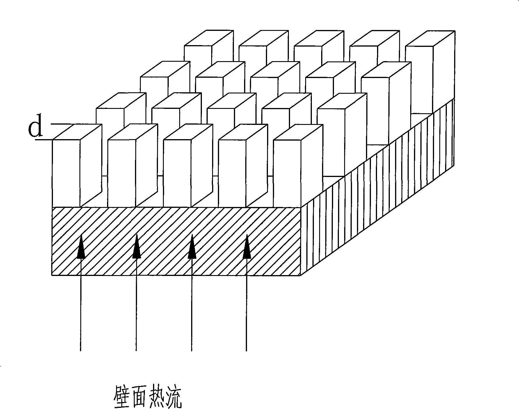
[0019] The specific implementation manners of the present invention will be further described in detail below in conjunction with the drawings and examples.

[0020] refer to figure 1 , the boiling heat exchange device for electronic components of the present invention includes: a heat dissipation plate fixed on the surface of the electronic components, a metal foam layer is sintered on the heat dissipation plate, and a square column microstructure with a width d of 50 μm to 200 μm is provided on the metal foam , the mutual spacing of the square column microstructures is 50 μm to 200 μm; wherein, the metal foam layer is a copper foam layer or an aluminum foam layer, the heat dissipation plate is a copper plate or an aluminum plate, and the heat dissipation plate is bonded to the surface of the electronic component through insulating and heat-conducting silica gel.

[0021] The opening of the square column microstructure is realized by laser marking technology. Laser marking t...


PUM

PropertyMeasurementUnit
widthaaaaaaaaaa
porosityaaaaaaaaaa

Abstract

The invention relates to the research field of boiling phase change heat transfer, in particular to a boiling heat transfer device of an electronic component. The boiling heat transfer device comprises a cooling plate fixed to the surface of the electronic component, a metal foam layer is sintered or welded on the upper surface of the cooling plate, the metal foam layer is provided with square column type microstructures with the width of 50 micron to 200 micron, and the interval between the square column type microstructures is 50 micron to 200 micron.

Description

technical field [0001] The invention relates to the field of boiling phase change heat transfer research, in particular to a boiling heat exchange device for electronic components. Background technique [0002] With the rapid development of power electronics technology, the requirements for high frequency, high speed and high integration of electronic components are getting higher and higher. The high temperature working environment will inevitably affect the performance of electronic components, which requires more efficient cooling. meet its requirements. Therefore, effectively solving the heat dissipation problem of electronic components has become a key technology in the manufacture of electronic components and electronic equipment. [0003] At present, the use of liquids to cool electronic chips has attracted widespread attention from many scholars at home and abroad, especially the electronic chips are directly immersed in non-conductive liquids and cooled by boiling ...

Claims


Application Information

Patent Timeline
Patent Type & Authority Applications(China)
IPC IPC(8): H05K7/20H01L23/367
Inventor 魏进家薛艳芳方嘉宾高秀峰
Owner XI AN JIAOTONG UNIV
Learn More