Automatic anti-backlash worm wheel dividing mechanism
An indexing mechanism and anti-backlash technology, applied in metal processing mechanical parts, precision positioning equipment, metal processing equipment, etc., can solve the problems that the indexing mechanism is difficult to achieve accuracy, cannot eliminate gaps, etc., to eliminate non-uniqueness, eliminate The effect of radial clearance of worm gear bearing and improving repeatability
- Summary
- Abstract
- Description
- Claims
- Application Information
AI Technical Summary
Problems solved by technology
Method used
Image
Examples
Embodiment 1
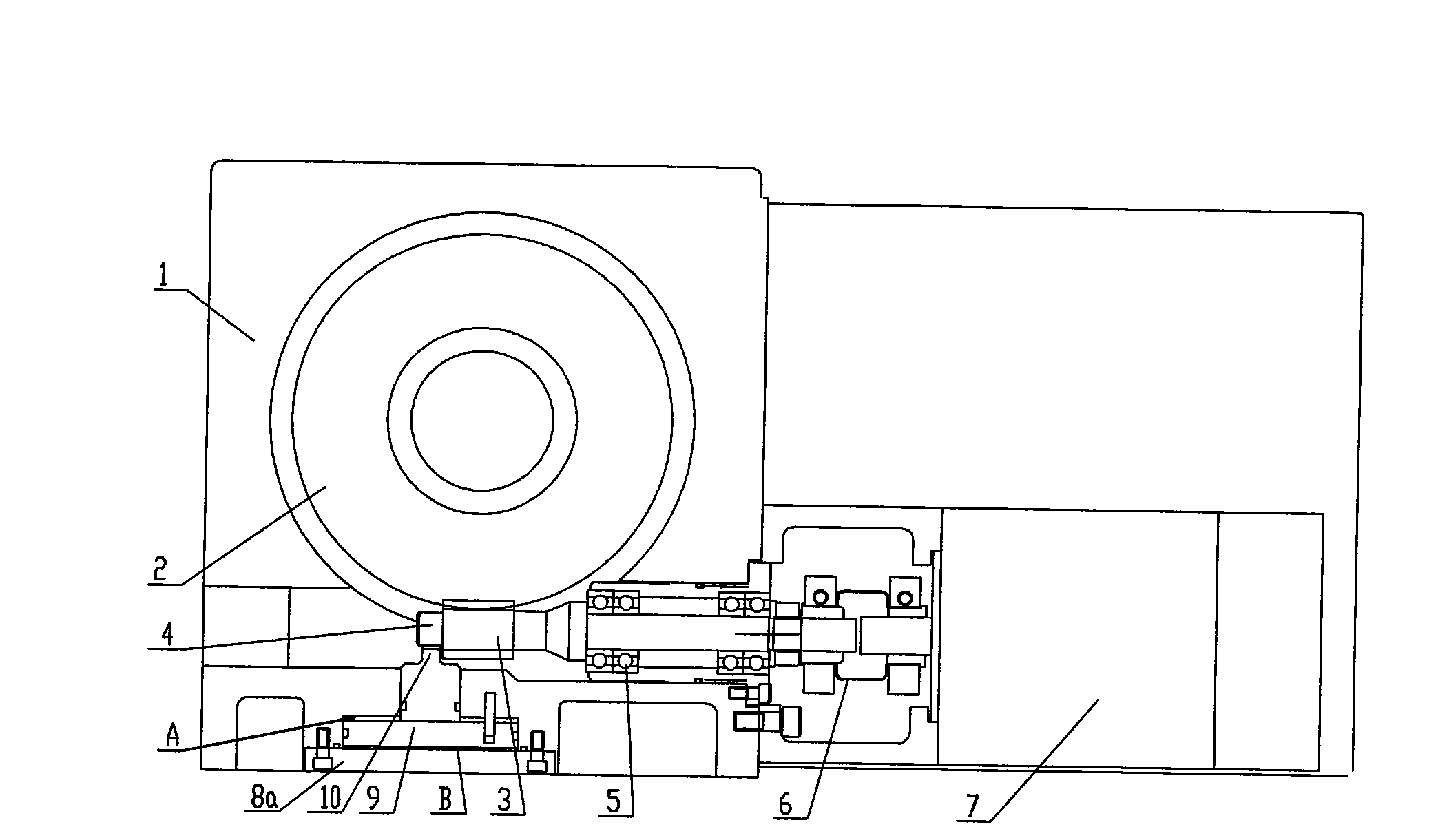
[0028] see figure 1 , In this embodiment, a worm wheel 2 and a worm 3 meshing with each other are set in the box 1, and the servo motor 7 is connected to the worm 3 through a coupling 6.
[0029] In this embodiment, the anti-backlash mechanism adopts a hydraulic mechanism, which is composed of a piston 9 with a piston rod, a cylinder body and a cylinder cover 8a, and the axis of the piston 9 is installed perpendicular to the axis of the worm. When the indexing mechanism is rotated and indexed, the cylinder A chamber in the hydraulic mechanism enters oil and chamber B returns oil, the piston 9 retracts, and the pressurized contact 10 breaks away from the contact with the pressure bearing surface 4 of the worm; when positioning is required after rotation, Cavity B of the oil cylinder in the hydraulic mechanism enters pressure oil, chamber A returns oil, the piston 9 is pushed upwards, and the pressurized contact 10 contacts the outer circle of the pressure bearing surface 4 of t...
Embodiment 2
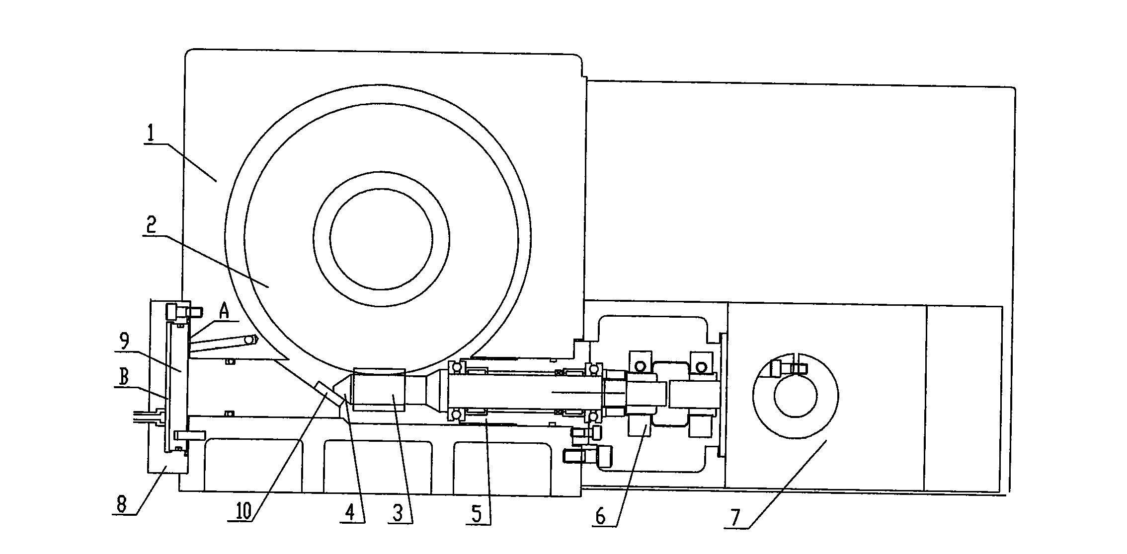
[0033] see figure 2 In this embodiment, a worm wheel 2 and a worm 3 meshing with each other are also provided in the box body 1 , and the servo motor 7 is connected to the worm 3 through a coupling 6 .
[0034] In this embodiment, the anti-backlash mechanism is an oil cylinder or an air cylinder, and the oil cylinder or air cylinder is formed by the piston 9 and the cylinder body 8 . The piston 9 is installed coaxially with the worm 3, and this structural form can simplify the processing technology of the housing;
[0035] In this embodiment, the end face of the pressure contact 10 is an inclined surface, the pressure bearing surface 4 of the worm is a conical surface coaxial with the worm, and the inclined surface on the pressure contact 10 is parallel to the generatrices of the conical surface 4 of the pressure contact 4 of the worm .
[0036] When rotating and indexing, the oil cylinder A chamber of the anti-backlash mechanism enters the oil, and the B chamber returns oi...
Embodiment 3
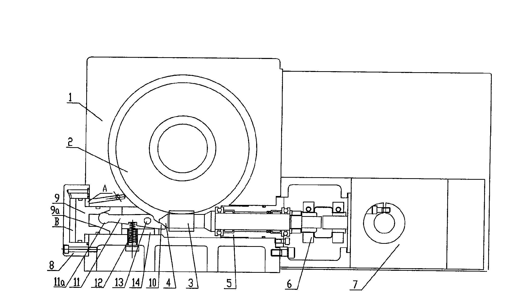
[0039] see image 3 In this embodiment, a worm wheel 2 and a worm 3 meshing with each other are also provided in the box body 1 , and the servo motor 7 is connected to the worm 3 through a coupling 6 .
[0040] The anti-backlash mechanism in this embodiment is composed of a cylinder and a mechanical booster, and is installed coaxially with the worm. touch.
[0041] image 3As shown, the right end push rod of the piston 9 has a tapered hole 9a, the booster lever 11 is installed in the casing 1 with the lever shaft 13 and the lever support 14, and the effect of the return spring 12 makes the booster lever 11 rod end The pressure contact 10 leaves the pressure bearing surface 4 of the worm. When the air in the chamber A and the air in the chamber B return, the piston 9 moves to the left, so that the booster lever 11 can swing clockwise under the action of the return spring 12, so the pressure contact 10 leaves the pressure bearing surface 4 of the pot rod, at this time There ...
PUM
 Abstract
Description
Claims
Application Information
 - R&D
- Intellectual Property
- Life Sciences
- Materials
- Tech Scout
- Unparalleled Data Quality
- Higher Quality Content
- 60% Fewer Hallucinations
Browse by: Latest US Patents, China's latest patents, Technical Efficacy Thesaurus, Application Domain, Technology Topic, Popular Technical Reports.
© 2025 PatSnap. All rights reserved.Legal|Privacy policy|Modern Slavery Act Transparency Statement|Sitemap|About US| Contact US: help@patsnap.com


