A rotating device for axially floating and radially preloading and fixing a rotating body where an inertial element is located

An inertial element and rotating body technology, applied in the field of inertial measurement, can solve the problems of reducing the stability of the rotating body, inability to rotate the modulation technology with errors, and reducing the effective accuracy of the inertial element.

Active Publication Date: 2018-08-24
SHAANXI BAOCHENG AVIATION INSTR
View PDF9 Cites 0 Cited by
  • Summary
  • Abstract
  • Description
  • Claims
  • Application Information

AI Technical Summary

Problems solved by technology

However, due to the difference in materials, tolerances and other factors between the rotating body and the non-rotating body, the gap between the rotating body and the non-rotating body will change differently as the temperature changes, which will greatly reduce the rotation of the rotating body. stability (when the gap is small, there is a possibility of jamming and stalling, when the gap is large, the rotating body will swing), reduce the effective accuracy of the inertial components, and cannot make the error rotation modulation technology play its due role, so there is Necessary to make improvements

Method used


Image

  • A rotating device for axially floating and radially preloading and fixing a rotating body where an inertial element is located
  • A rotating device for axially floating and radially preloading and fixing a rotating body where an inertial element is located
  • A rotating device for axially floating and radially preloading and fixing a rotating body where an inertial element is located

Examples


Embodiment Construction

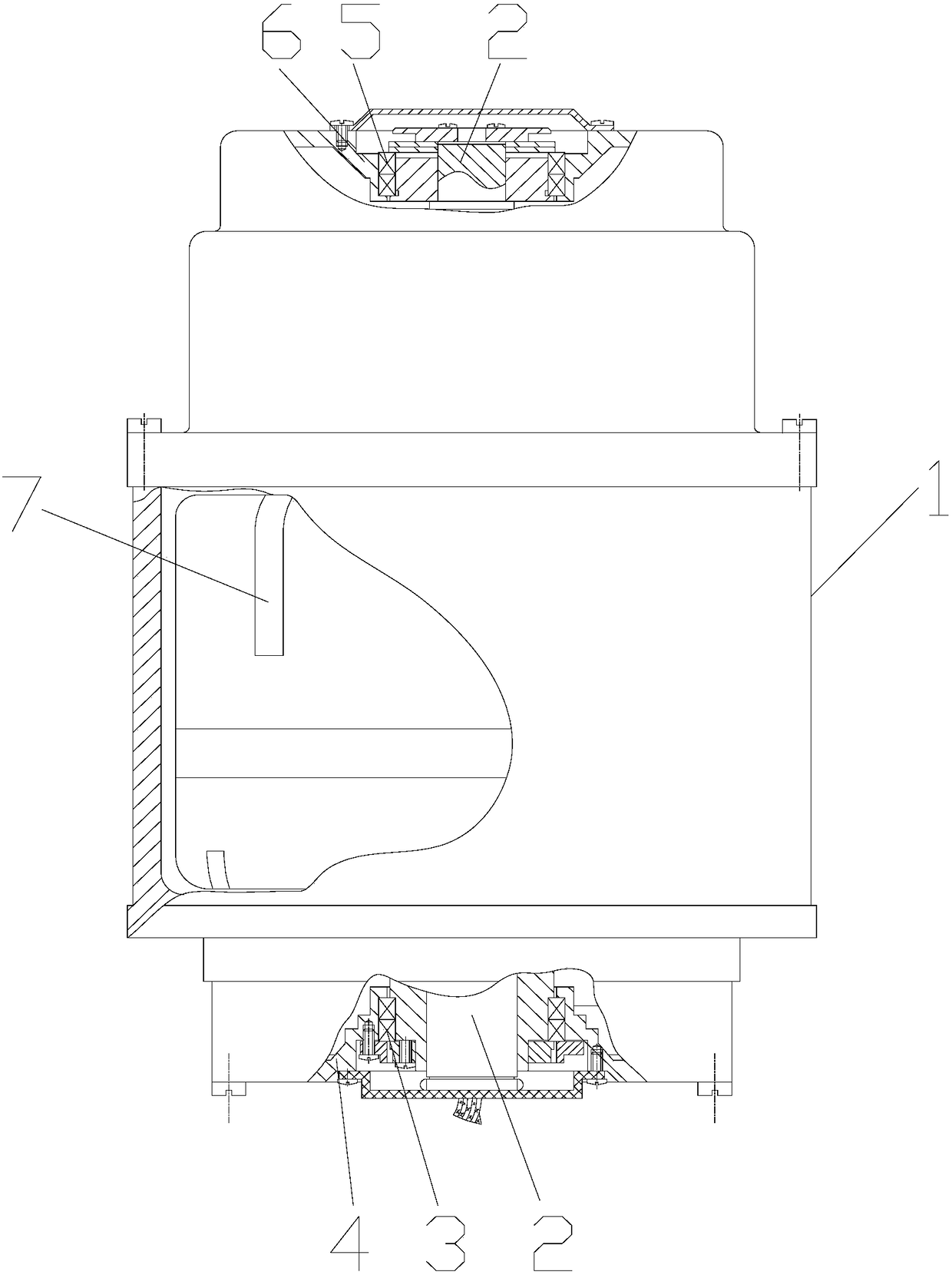
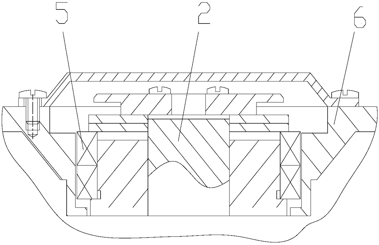
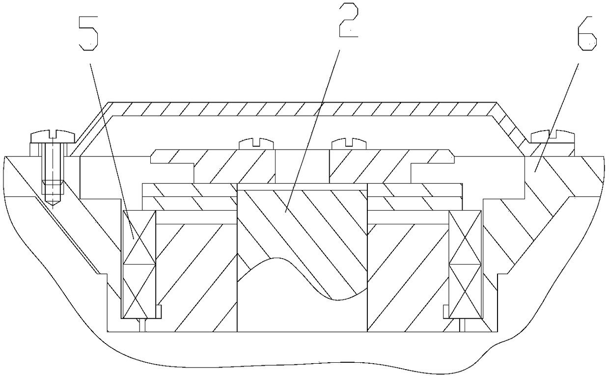
[0016] Attached below Figure 1-4 An embodiment of the present invention is described.

[0017] A device for axially floating, radially pre-tightening and fixing the rotating body where the inertial element is located. It has a non-rotating body 1 and a rotating body 2. The inertial element 7 is installed in the rotating body 2. The lower end of the rotating body 2 is supported by the lower bearing 3 on the On the non-rotating body 1, and the lower bearing 3 is fixed in the lower bearing seat 4, the upper end of the rotating body 2 is supported on the non-rotating body 1 through the upper bearing 5, and when the rotating body 2 is heated or cold, the upper bearing 5 and the upper The bearing seat 6 is floatingly connected, specifically, the outer ring 9 of the upper bearing 5 is in clearance fit with the wall surface of the inner hole of the upper bearing seat 6 , and the upper bearing 5 is fixed on the rotating shaft 8 at the top of the rotating body 2 . At the same time, a ...


PUM


Abstract

Provide a device for axially floating, radially pre-tightening and fixing the rotating body where the inertial element is located, which has a non-rotating body and a rotating body, the inertial element is installed in the rotating body, the lower end of the rotating body is supported on the non-rotating body through a lower bearing, and The lower bearing is fixed in the lower bearing seat, and the upper end of the rotating body is supported on the non-rotating body through the upper bearing, and the rotating body is floatingly connected in the upper bearing seat so that the rotating body and the non-rotating body can be displaced mutually when heated or cooled, expanding or contracting, At the same time, a compensating device for constraining the radial gap between the upper bearing and the rotating body is provided on the inner hole wall of the upper bearing seat. Adopting this technical scheme can accurately adjust the axial gap between the rotating body and the non-rotating body under the condition of great changes in the ambient temperature, and can also eliminate the radial gap between the rotating body and the bearing, the outer ring of the bearing and the non-rotating body. To the gap, the rotating body rotates smoothly in the non-rotating body, the expected error rotation modulation result is obtained, and the effective precision of the inertial element is improved.

Description

technical field [0001] The invention belongs to the technical field of inertial measurement, and in particular relates to a device for axially floating and radially pre-tightening and fixing a rotating body where an inertial element is located. Background technique [0002] In order to improve the effective precision of the inertial element, under normal circumstances, the error rotation modulation technology can be used to make the rotating body where the inertial element is located rotate at a uniform speed, and better results can be obtained. However, due to the difference in materials, tolerances and other factors between the rotating body and the non-rotating body, the gap between the rotating body and the non-rotating body will change differently as the temperature changes, which will greatly reduce the rotation of the rotating body. stability (when the gap is small, there is a possibility of jamming and stalling, when the gap is large, the rotating body will swing), r...

Claims


Application Information

Patent Timeline
Patent Type & Authority Patents(China)
IPC IPC(8): F16C35/12
CPCF16C35/12
Inventor 赵治伟陈磊江马英华胡安禄赵红敏陈国品狄金华杨杰刘剑锋郑群英张卫杰赵永康
Owner SHAANXI BAOCHENG AVIATION INSTR
Why Eureka
Try Eureka