
link chain

A technology of link chains and inner link plates, which is applied in the field of link chains, can solve the problems of material selection or size design structural space restrictions and restrictions, and achieve the effect of optimizing axial fixation and enhancing effects

Active Publication Date: 2022-07-29
KETTEN WULF BETRIEBS GMBH & CO KG
View PDF11 Cites 0 Cited by
  • Summary
  • Abstract
  • Description
  • Claims
  • Application Information

AI Technical Summary

Problems solved by technology

However, the choice of material or dimensioning is limited, for example, by the available construction space and ultimately also by the reasonable cost of the link chain

Method used


Image

  • link chain
  • link chain
  • link chain

Examples


Embodiment Construction

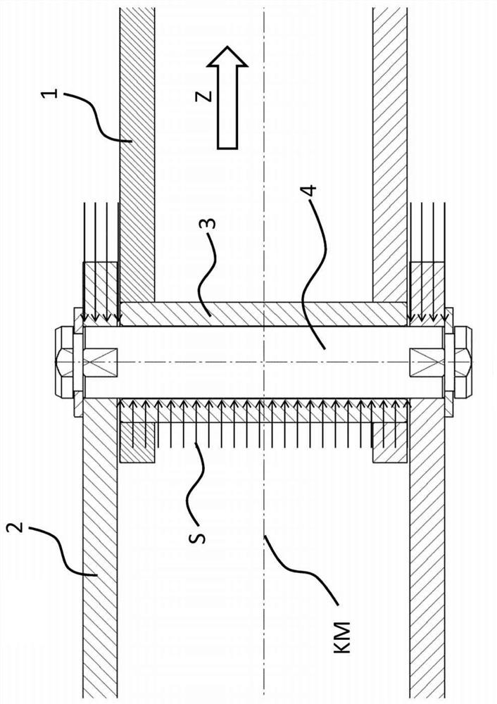
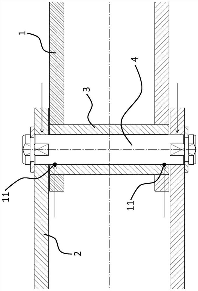
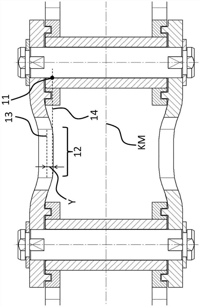
[0050] The following reference numbers are used in the figures:

[0051] 1 Internal connection board

[0052] 2 External connection board

[0053] 3 Sleeves

[0054] 4 pins

[0055] 5 holes

[0056] KM Chain Centerline / Chain Centerline

[0057] L Longitudinal axis of connecting plate / Longitudinal line of connecting plate

[0058] LM connecting plate center line / connecting plate center line

[0059] LMQ connecting plate central axis cross section

[0060] Center point of hole B

[0061] BM Hole Centerline / Hole Centerline

[0062] BMQ hole wall cross section

[0063] 11 Points of force transmission

[0064] 12 Sections of the outer connecting plate

[0065] 13 Section Centerlines

[0066] 14 Line through point 11

[0067] Y distance between chain centerline and offset centerline

[0068] Z pull direction

[0069] S Uniform load

[0070] 21 Waist in

[0071] 22 Areas removed

[0072] 31 Reinforced areas / reinforcements / thickenings

[0073] 41 Boss / Ring

[0...


PUM


Abstract

The invention relates to an articulated chain comprising at least an inner connecting plate (1), an outer connecting plate (2), a sleeve (3) and a pin (4) forming a chain joint, wherein the external connection is A labyrinth sealing device is arranged between the plate (2) and the inner connecting plate (1), the labyrinth sealing device comprises at least one raised part (41) and at least one groove (42), wherein the at least one raised part (41) and at least one A groove ( 42 ) is formed in length (LN) or depth (TN) between 10% and 50% of the corresponding average web thickness (D), and wherein the labyrinth seal is designed such that it is In the event of overloading, the path of the force flow within the articulated chain is partially changed by the labyrinth surface formed by the at least one projection (41) and the at least one groove (42).

Description

technical field [0001] The present invention relates to an articulated chain. Background technique [0002] An articulated link chain, in particular a sleeve chain, essentially consists of two elements which are arranged endlessly on one another. These elements are also referred to as inner and outer link plates. The outer link plates generally comprise two outer connecting plates, which are fixedly connected to each other by two pins. The inner link plate is usually composed of two inner connecting plates and two sleeves, which respectively form a chain joint with the pins of the adjacent outer link plates. These joints enable the joint chain, for example, to be wound around sprockets in the drive train. [0003] An important criterion for the use of an articulated chain is its transmittable tensile force. In principle, corresponding transmittable tensile forces are achieved, for example, by the material selection, heat treatment and material thickness of the individual...

Claims


Application Information

Patent Timeline
Patent Type & Authority Patents(China)
IPC IPC(8): F16G13/06
CPCF16G13/06F16G15/00F16G13/02
Inventor T·赫贝克尔T·乌尔夫
Owner KETTEN WULF BETRIEBS GMBH & CO KG
Learn More