Hydraulic filter element and related method of manufacture

A filter element and hydraulic technology, which is applied in the field of manufacturing such hydraulic filter elements and oil filter elements, can solve problems such as installation and removal costs, high time costs, etc., to reduce costs, improve functionality, and prevent damage or destruction Effect

Active Publication Date: 2016-05-04
上海弗杰过滤器材有限公司
View PDF7 Cites 0 Cited by
  • Summary
  • Abstract
  • Description
  • Claims
  • Application Information

AI Technical Summary

Problems solved by technology

The installation and removal of such tensioning elements requires time-consuming and relatively cost-intensive manufacturing steps

Method used


Image

  • Hydraulic filter element and related method of manufacture
  • Hydraulic filter element and related method of manufacture
  • Hydraulic filter element and related method of manufacture

Examples


Embodiment Construction

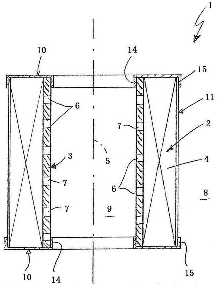
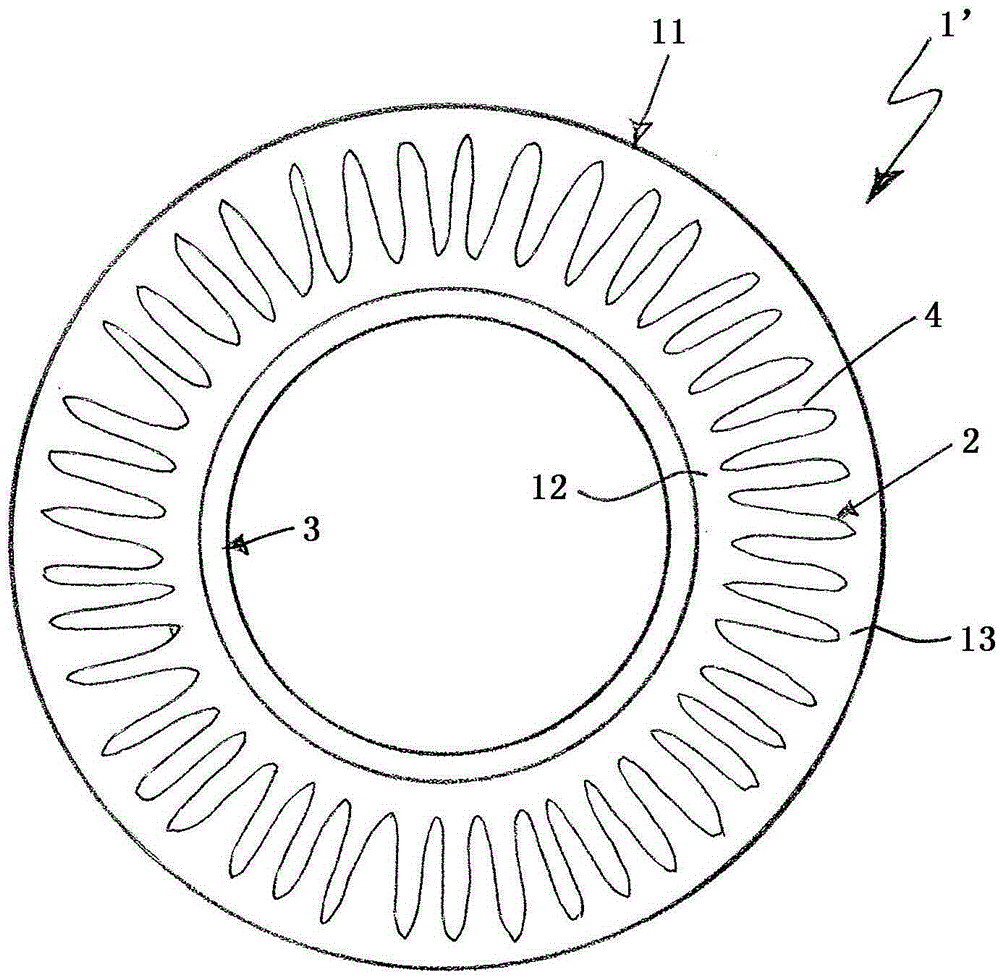
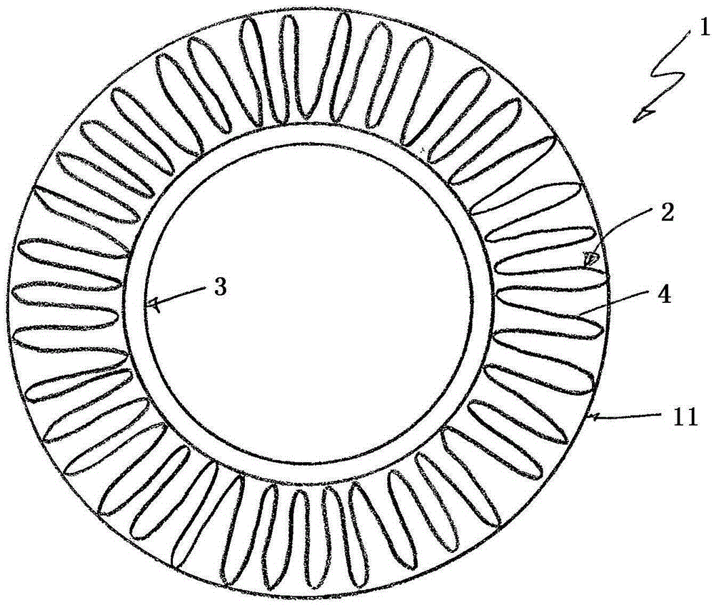
[0032] and Figure 1 to Figure 3 Correspondingly, the hydraulic filter element 1 , which may preferably be an oil filter element, comprises a cylindrical filter body 2 and a cylindrical inner frame 3 . The filter body 2 is produced by means of a star-shaped folded filter material 4 . The inner frame 3 is arranged coaxially with the filter body 2 , wherein the filter body 2 surrounds the inner frame 3 . exist figure 1 The common longitudinal center axis is marked with reference numeral 5 . The inner frame 3 is designed to be permeable to the respective hydraulic medium, especially oil. For this purpose, the inner frame can be formed with a perforation 6 consisting of a plurality of individual through-openings 7 . The filter body 2 is supported radially inwardly on the inner frame 3 . The filter body 2 can thus withstand a relatively large pressure difference between the external raw space 8 and the internal clean space 9 during operation.

[0033] In the example, hydrauli...


PUM

PropertyMeasurementUnit
diameteraaaaaaaaaa
thicknessaaaaaaaaaa
thicknessaaaaaaaaaa

Abstract

The invention relates to a hydraulic filter element (1), in particular an oil filter element, with a cylindrical filter body (2) made of star-shaped folded filter material (4) and a cylindrical Shaped inner frame (3), on which the filter body (2) is supported radially inwardly. A simplified production of the hydraulic filter element results in that a cylindrical sleeve ( 11 ) permeable to the respective hydraulic medium is provided, which rests radially outward on the filter body ( 2 ).

Description

technical field [0001] The invention relates to a hydraulic filter element, especially an oil filter element. The invention also relates to a method for producing such a hydraulic filter element. Background technique [0002] Hydraulic filter elements usually have a cylindrical filter body made of filter material folded in a star shape. Due to the large pressure differences that occur between the external raw side and the internal clean side during use, such hydraulic filter elements can additionally be equipped with a cylindrical inner frame in which the filter body can be supported radially inwardly. on the box. Furthermore, axial end disks can be provided which are arranged at opposite axial ends of the filter body. [0003] During the production of such hydraulic filter elements, an inner frame is inserted into the folded filter material, and the filter material is prestressed against the inner frame by means of tensioning elements, such as belts, ropes or the like. ...

Claims


Application Information

Patent Timeline
Patent Type & Authority Patents(China)
IPC IPC(8): B01D29/11B01D29/21B01D29/58
CPCB01D29/111B01D29/21B01D29/58B01D39/08B01D2201/127B01D2239/0654B01D2239/0668B01D2239/069B01D2239/10B01D29/11
Inventor 威廉·舍普赖因哈特·维尔林
Owner 上海弗杰过滤器材有限公司
Why Eureka
Try Eureka