
Upgrading and modifying method for laser surface of drawing mould

A technology for surface modification and deep drawing of dies, applied in laser welding equipment, forming tools, furnace types, etc., can solve problems such as metal-to-metal adhesion, lubricating oil film crushing, wear failure, etc., to improve the lubrication condition of the die surface, Good repeatability of microtopography and improved wear resistance

Inactive Publication Date: 2009-09-23
JIANGSU UNIV
View PDF0 Cites 12 Cited by
  • Summary
  • Abstract
  • Description
  • Claims
  • Application Information

AI Technical Summary

Problems solved by technology

The condition that the drawing die size is out of tolerance and cannot be used due to repeated wear and trimming is a wear failure
When the processed part is in contact with the surface of the mold under pressure, microscopically, it is firstly the contact of the convex peaks on the surface, and its actual contact area is much smaller than the nominal contact area. Therefore, the actual specific pressure of some contact points is very large. Extrusion plastic deformation occurs, and the lubricating oil film and oxide film at the contact point are crushed, resulting in direct contact between metals and adhesion, making it difficult for parts to be demolded

Method used


Image

  • Upgrading and modifying method for laser surface of drawing mould
  • Upgrading and modifying method for laser surface of drawing mould

Examples


Embodiment Construction

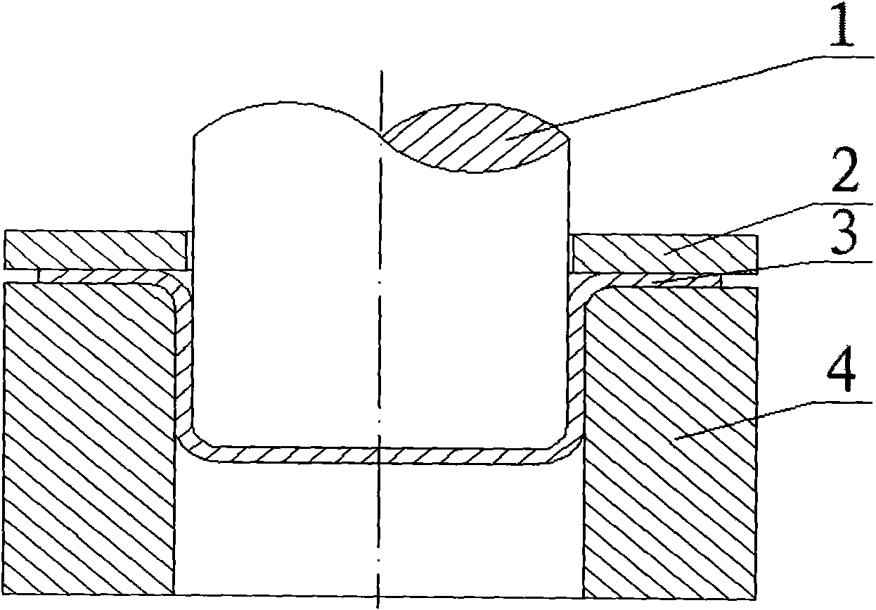
[0016] Such as figure 1 , The drawing die is composed of three parts: the die 4 , the punch 1 and the blank holder 2 , and the workpiece 3 is located between the die 4 and the punch 1 . Implementation steps of the present invention are:

[0017] 1. Select laser processing equipment. The laser processing equipment uses Nd-doped yttrium aluminum garnet laser (Nd:YAG pulsed laser), its basic parameters are: the maximum average power is 500W, the pulse width is 0.5-9ms, and the pulse frequency range is 1-100Hz.

[0018] 2. Select the base of the drawing die. The drawing die material is high carbon chromium bearing steel, namely GCr15.

[0019] 3. Drive the laser and adjust the laser power density to 10 4 ~10 6 W / cm 2 , pulse width, pulse frequency and other laser parameters, so that the pulse laser with high energy density and high repetition frequency irradiates the working surface of the drawing die, and at the same time the working surface of the drawing die moves along t...


PUM

PropertyMeasurementUnit
diameteraaaaaaaaaa
poweraaaaaaaaaa
frequencyaaaaaaaaaa

Abstract

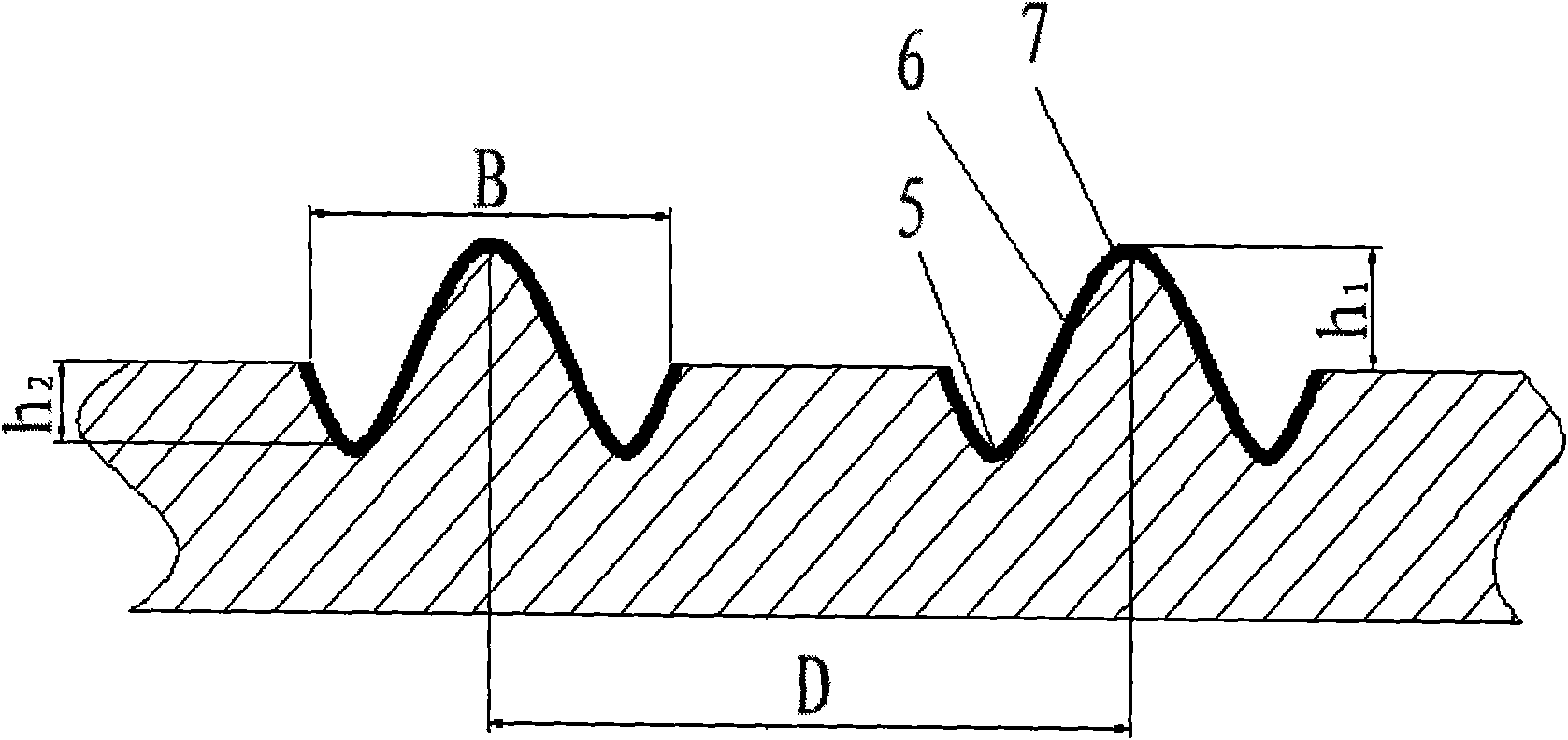
The invention discloses an upgrading and modifying method for a laser surface of a drawing mould. Laser machining equipment is adopted to drive a pulsed laser, and pulsed lasers irradiate the working surface of the drawing mould; the working surface of the drawing mould moves along the pulsed lasers to blow out auxiliary gas; each microsphere coronary unit body consisting of a pit and a pit side lug boss is formed on the working surface of the drawing mould, the height difference of each microsphere coronary unit body and the working surface of the drawing mould is ranged from 2.86 microns to 3.58 microns, and the microsphere coronary unit bodies are continuously and uniformly arranged on the working surface of the drawing mould. The height difference of the pit and the working surface of the drawing mould is ranged from 2.15 microns to 2.69 microns, the diameter of each microsphere coronary unit body is ranged from 210 microns to 280 microns, and the distance between every two adjacent microsphere coronary unit bodies is ranged from 300 microns to 500 microns. The invention adopts the upgrading and modifying technology for the laser surface, manufactures micro-morphology arrangement of micro pits and micro lug bosses on the surface of the drawing mould, has no pollution in a machining process, and can remarkably improve the wear resistance and the demoulding performance of the surface of the drawing mould.

Description

technical field [0001] The invention relates to the field of metal plastic forming moulds, in particular to a method for performing laser surface modification on the molding working surface of the mould. Background technique [0002] Mold is an indispensable and important process equipment in industrial production, and it is the basis and guarantee for reducing costs, improving product quality and adapting to large-scale production. In order to improve production efficiency and material utilization, and reduce parts processing links, the requirements for the development of high precision and long life are put forward for molds. Among them, improving the service life of the mold is the top priority in the development of the mold industry. Using modern high-tech means to prepare high-performance new molds can prolong the service life of the mold, avoid premature failure, and reduce unnecessary losses. It has significant economic benefits. . [0003] Drawing dies are mainly u...

Claims


Application Information

Patent Timeline
Patent Type & Authority Applications(China)
IPC IPC(8): B23K26/38B23K26/08B23K26/14C21D9/00C21D1/09B21D37/10B21D22/20
Inventor 骆志高郭啸栋范彬彬
Owner JIANGSU UNIV
Learn More