Electromagnetic magnetoelectric-effect type sensor
A magnetoelectric effect and sensor technology, which is applied in the field of electromagnetic non-destructive testing devices for ferromagnetic components, can solve problems such as inconvenient application and operation, limited quantitative resolution, large and bulky probe circuit devices, etc., and achieves the advantages of wide use, high performance and price advantage Effect
- Summary
- Abstract
- Description
- Claims
- Application Information
AI Technical Summary
Problems solved by technology
Method used
Image
Examples
Embodiment 1
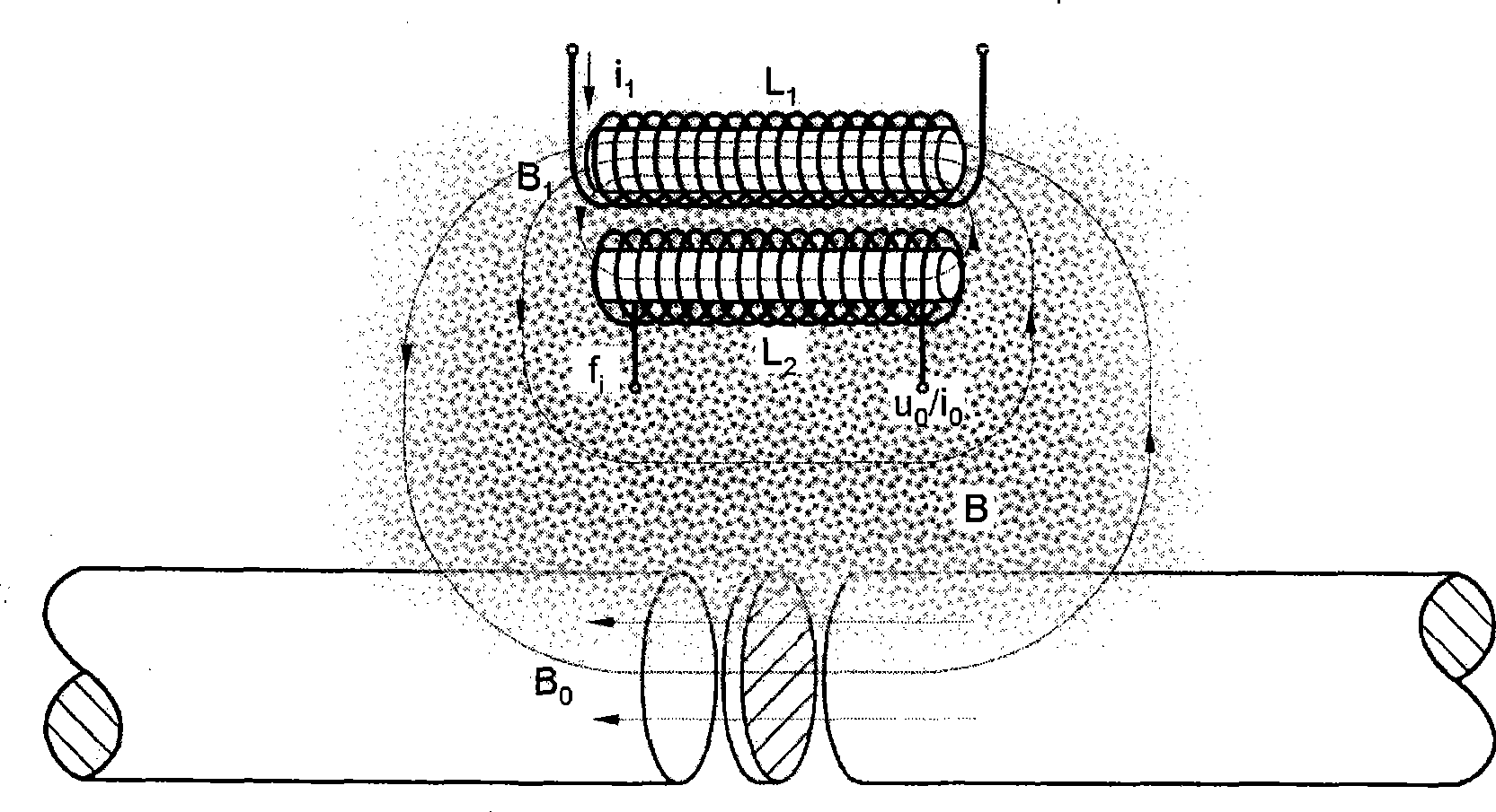
[0019] Such as figure 1 Shown in, a kind of electromagnetic magnetoelectric effect type sensor described in the present invention, adopts by electromagnetic release coil L 1 and magnetic energy balance coil L 2 An electromagnetic magnetoelectric effect sensor is formed; it is characterized in that: ① The sensor has the characteristics of "double electric double magnetic" circuit distribution in terms of technical principle, that is, the electromagnetic circuit design has dual output of excitation current and magnetic energy potential pressure difference. Loop, magnetoelectric circuit design has energy release electromagnetic field and magnetic energy balance coil L 2 The external spatial magnetic field correlates with the nested double loops, and correlates the responses through the nested magnetic circuits. ② Electromagnetic release coil L of the sensor 1 , Magnetic energy balance coil L 2 , all adopt high magnetic permeability magnetic cores, placed adjacent to each othe...
Embodiment 2
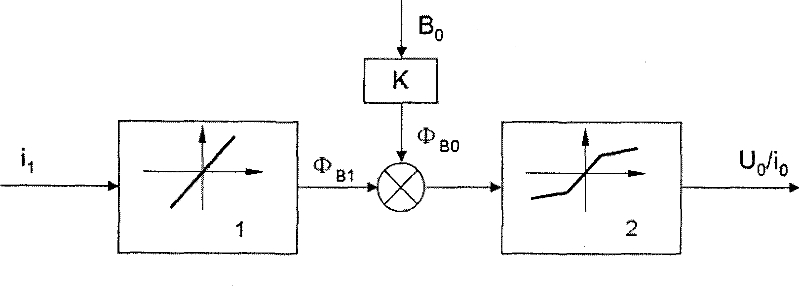
[0021] Such as figure 2 Shown in, a kind of electromagnetic magnetoelectric effect type sensor of the present invention: 1. the non-saturation characteristic provided by the magnetic core of electromagnetic release coil L1 is equivalent to a linear link, and its input is constant direct current i 1 generate B 1 . ② Stable and weak magnetic field B of ferromagnetic components 0 with B 1 The associated magnetic field B is generated when the space interacts, and the magnetic energy balance coil L 2 In the associated magnetic induction field B. ③Magnetic energy balance coil L 2 , due to the saturation-amplitude characteristics provided by its magnetic core, it is equivalent to a double-gain nonlinear link, and its input is the associated induced magnetic flux Φ B =Constant current flux Φ B1 + Response flux Φ B0 , the output is level u 0 . ④ The system composed of ①②③ each link realizes the self-controlled conversion between the input variable and the output variable, an...
Embodiment 3
[0023] Such as figure 1 As shown in , the electromagnetic release coil L used by the sensor 1 674 turns φ0.05mm copper wire coil, φ2.5mm (section diameter)×40mm (length) microcrystalline magnetic core; magnetic energy balance coil L 2 It is 796 turns of φ0.2mm copper wire coil, φ2mm (cross-sectional diameter)×30mm (length) permalloy magnetic core, electromagnetic release coil L 1 , Magnetic energy balance coil L 2 It is fixed by a steel frame and placed in parallel, with a center distance of 6.30±0.04mm.
[0024] Low voltage (5V) weak current (-1 mT=10 -4 The higher resolution of T) is less affected by the lift-off effect, and the upper limit of the distance from the surface of the magnetic component can reach 5cm during measurement, and it can not be affected by the small vibration of the component system and the change of relative motion speed during the detection; it is reliable , Simple, economical and durable, not only can be widely used, but also the manufacturing cost...
PUM
 Abstract
Description
Claims
Application Information
 - Generate Ideas
- Intellectual Property
- Life Sciences
- Materials
- Tech Scout
- Unparalleled Data Quality
- Higher Quality Content
- 60% Fewer Hallucinations
Browse by: Latest US Patents, China's latest patents, Technical Efficacy Thesaurus, Application Domain, Technology Topic, Popular Technical Reports.
© 2025 PatSnap. All rights reserved.Legal|Privacy policy|Modern Slavery Act Transparency Statement|Sitemap|About US| Contact US: help@patsnap.com


