Method and apparatus for working a screw rotor, end mill for working , and method of manufacturing a screw compressor
一种加工方法、端铣刀的技术,应用在加工装置,端铣刀领域,能够解决易产生误差、生产、不能螺旋转子等问题,达到提高精度、加工简单的效果
- Summary
- Abstract
- Description
- Claims
- Application Information
AI Technical Summary
Problems solved by technology
Method used
Image
Examples
Embodiment approach 1
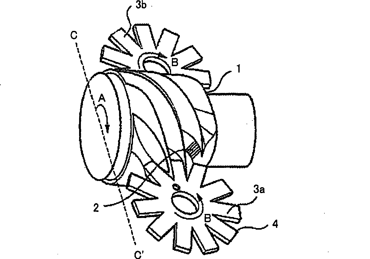
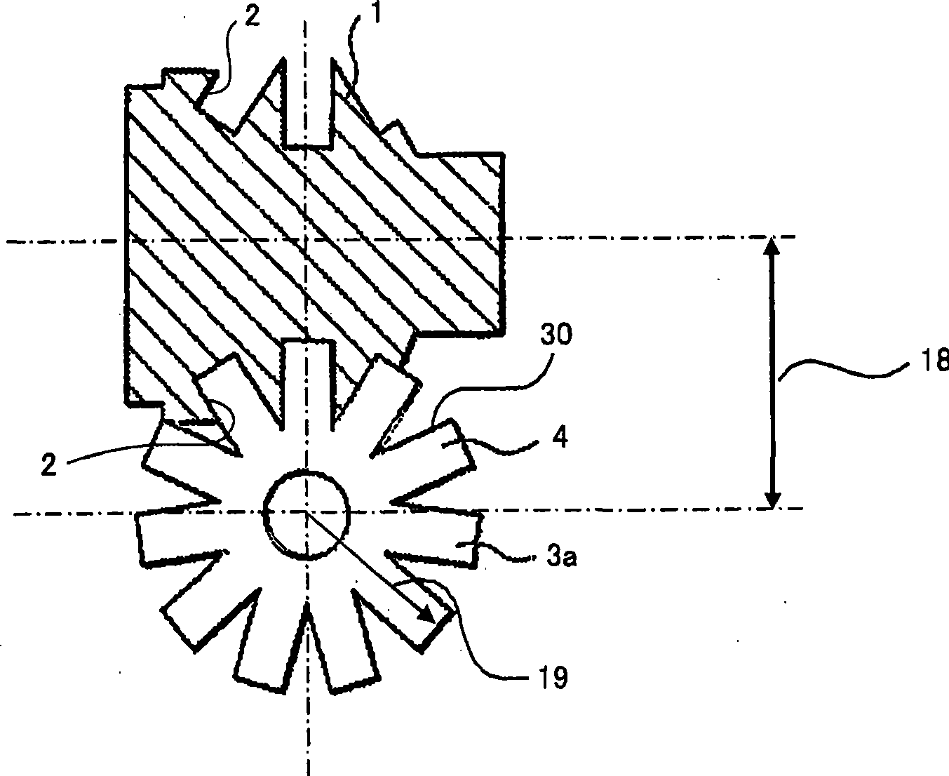
[0062] First, according to figure 1 , first explain the compression principle of the single screw compressor. In the single screw compressor, a screw rotor 1 having a plurality of slots 2 and gate rotors 3a, 3b having a plurality of teeth 4 are arranged symmetrically to each other at right angles to the axis. exist figure 1 The case where the helical rotor 1 has six tooth slots 2 and the gate rotors 3 a , 3 b have eleven teeth 4 is illustrated in . A case (not shown) is covered on the outer periphery of the screw rotor 1, and a closed space is formed on the inner diameter of the case by the tooth slots 2 of the screw rotor 1 and the teeth 4 of the gate rotors 3a, 3b. At a certain position of the helical rotor 1, the refrigerant gas is sucked into the cog 2, and the cog 2 is closed by the door rotors 3a, 3b that rotate with the rotation of the helical rotor 1, thereby sealing the refrigerant gas.
[0063] Furthermore, when the screw rotor 1 rotates, the volume of the tooth s...
Embodiment approach 2
[0086] In Embodiment 1, the case where the fourth end mill 27 is used in the tooth groove side surface finishing step is described, and in Embodiment 2, the sixth end mill 50 having a smaller diameter than the first end mill 25 is used as the tool use. The first step is to use the first end mill 25 as a tool to make a certain slit in the depth direction of the helical groove to the desired depth. The second end mill with a smaller diameter than the first end mill is used as a tool. The second step of rough machining the side surface of the spiral tooth groove, and the third step of processing the bottom surface of the spiral tooth groove by using the third end mill having an R shape at the front end as a tool are the same as in the first embodiment. , to avoid repetition, the description is omitted.
[0087] The case where the sixth end mill 50 is used is shown in Figure 21 , Figure 22 middle. Figure 21 is a diagram illustrating the lead and tool position in finishing, ...
PUM
 Abstract
Description
Claims
Application Information
 - Generate Ideas
- Intellectual Property
- Life Sciences
- Materials
- Tech Scout
- Unparalleled Data Quality
- Higher Quality Content
- 60% Fewer Hallucinations
Browse by: Latest US Patents, China's latest patents, Technical Efficacy Thesaurus, Application Domain, Technology Topic, Popular Technical Reports.
© 2025 PatSnap. All rights reserved.Legal|Privacy policy|Modern Slavery Act Transparency Statement|Sitemap|About US| Contact US: help@patsnap.com


