
Microwave chemical reaction device using dielectric radiator

A chemical reaction and radiator technology, applied in the field of microwave chemical reaction devices, can solve problems such as increased reflection of microwave energy, uneven temperature, damage, etc., to meet power and volume and pressure bearing capacity, reduce manufacturing costs, and improve uniformity Effect

Inactive Publication Date: 2009-09-02
SICHUAN UNIV
View PDF1 Cites 10 Cited by
  • Summary
  • Abstract
  • Description
  • Claims
  • Application Information

AI Technical Summary

Problems solved by technology

The utility model patent with the authorized announcement number CN 201108822Y, although the purpose of the invention is to provide a high-power, large-volume, high-pressure microwave chemical reaction device, but because its microwave transmission system consists of a circulator, a three-pin adjuster, and a matching load Composed of a waveguide section, the microwave is fed into the reactor (reaction vessel) through the microwave coupling window provided on the wall of the reaction vessel in the microwave chemical reaction device, and the microwave is freely propagated in the reaction vessel (compared with other existing microwave chemical reaction devices) There is no substantial difference in the microwave transmission system), so it is difficult to obtain a uniformly distributed microwave field in a large-capacity (volume) chemical reaction container, resulting in serious temperature unevenness in the material to be processed in the system, which affects the chemical reaction Effect
The reason is that during the free propagation of microwaves in the reaction vessel, most of the microwave energy is absorbed by the materials after a certain distance (compared with the radius of the vessel), and the materials in the area farther away from the feed port will Can not get effective microwave radiation
In addition, the existing microwave transmission system still has the following problems: During the chemical reaction, the dielectric constant of the reactant system will change, which will lead to a change in the impedance of the microwave feed port, and the use of pins for impedance matching cannot effectively track this. Therefore, the reflection of microwave energy will increase, causing the power output of the microwave source to be unstable or even damaged. The manufacturing cost of the reactor

Method used


Image

  • Microwave chemical reaction device using dielectric radiator
  • Microwave chemical reaction device using dielectric radiator
  • Microwave chemical reaction device using dielectric radiator

Examples


Embodiment 1

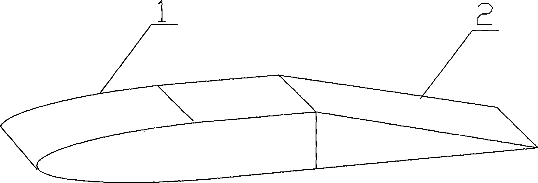
[0045] The microwave chemical reaction device in this embodiment works under normal pressure, the reaction vessel 5 is made of stainless steel, the volume of the reaction vessel is 30 liters, a set of microwave transmission system is set, the microwave source power is 1kW, and the microwave frequency is 2450MHz. The microwave transmission system includes a dielectric radiator 10 and a waveguide 8 . The structure of the dielectric radiator 10 is as figure 1 As shown, it is composed of radiation section 1 and impedance transformation section 2. The longitudinal section of radiation section 1 is a combination of semi-ellipse and rectangle. The longitudinal section of impedance transformation section 2 is a triangle. Radiation section 1 and impedance transformation section 2 are an integrated structure. (Integral structure), made of quartz glass. The waveguide 8 is a BJ-22 copper waveguide, and its end is provided with a flange 7 for connection. The assembly method of the reacti...

Embodiment 2

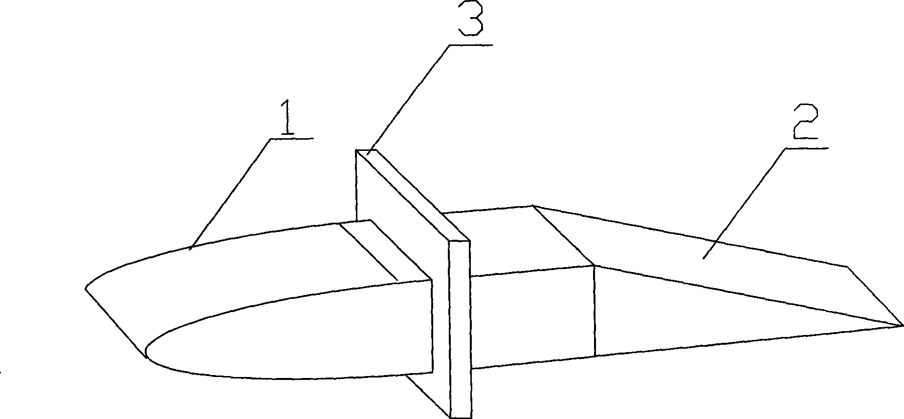
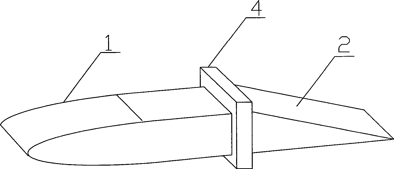
[0048] The microwave chemical reaction device in this embodiment works under pressure (pressure 1.5MPa), the power is 12kW, and the operating frequency is 2450MHz. Its reaction vessel 5 is made of stainless steel, and its volume is 300 liters, and its internal diameter is 90 centimeters. Four sets of Microwave transmission systems that are independent of each other and have the same structure, each microwave transmission system includes a dielectric radiator 10 and a waveguide 8 . The structure of the dielectric radiator 10 is as Figure 4 As shown, it consists of radiating section 1, impedance transformation section 2, fastening plate 3 and dielectric baffle 4, fastening plate 3 is located on radiating section 1 and is an integrated structure with radiating section 1, radiating section 1, dielectric baffle 4. Impedance transformation section 2 is manufactured separately and combined during installation; the longitudinal section of radiation section 1 is a combination of semi-...

Embodiment 3

[0053] The microwave chemical reaction device in this embodiment works under pressure (pressure 1.0MPa), the power is 90kW, and the operating frequency is 2450MHz. The reaction vessel 5 is made of stainless steel and has a volume of 2000 liters. There are 30 sets of five layers that are independent of each other. And the microwave transmission system with the same structure. The installation positions of 30 sets of microwave transmission systems on the reaction vessel 5 and the assembly methods of the dielectric radiator 10, waveguide 8 and microwave source 9 in each set of microwave transmission systems are as follows: Figure 10 , Figure 11 and Figure 12 shown. The five-layer microwave transmission system installed on the side wall of the reaction vessel 5 is installed at an interval of 30 cm along the axial direction of the reaction vessel. Each set of microwave transmission systems at the same height is installed at an interval of 60°, and two sets of microwave transmi...


PUM


Abstract

The invention provides a microwave chemical reaction device using a dielectric radiator, which comprises a reaction vessel and a microwave energy transmission system. The microwave energy transmission system comprises the dielectric radiator and a wave guide, wherein the dielectric radiator passes through the wall of the reaction vessel and extends into the reaction vessel; and the dielectric radiator is connected with a microwave source through the wave guide. The number of the microwave energy transmission systems is determined by the power and volume of the microwave chemical reaction device; for the microwave chemical reaction device with small power and volume, the microwave energy transmission systems can be one set or two sets, and for the microwave chemical reaction device with large power and volume, a plurality of independent microwave energy transmission systems can be arranged. When the microwave energy transmission systems are more than two sets, the position of the dielectric radiator in each set of the microwave energy transmission system in the reaction vessel can make energy coupling of the dielectric radiator and the other dielectric radiators in all microwave energy transmission systems be less than or equal to -10 dB.

Description

technical field [0001] The invention belongs to the field of microwave chemical reaction devices, in particular to a large-capacity microwave chemical reactor suitable for industrial production and working under high temperature and pressure environments. Background technique [0002] Microwave chemistry is an emerging frontier interdisciplinary subject that studies the application of microwaves in chemistry, and the microwave chemical reaction device is the key to the entire microwave chemical reaction system. Its design involves multidisciplinary knowledge and is also a complex engineering problem. . [0003] At present, there are many kinds of microwave chemical reaction devices at home and abroad, but most of them can only be used under normal temperature and pressure, and due to the limitations of small volume and low power, they are only suitable for scientific research in laboratories. Although some microwave chemical reaction devices can be used under high temperatu...

Claims


Application Information

Patent Timeline
Patent Type & Authority Applications(China)
IPC IPC(8): B01J19/12
Inventor 黄卡玛华伟杨晓庆刘长军陈星郭庆功闫丽萍赵翔
Owner SICHUAN UNIV
Learn More