
Plate heat exchanger

A technology of heat exchanger and heat conduction, which is applied in the field of adsorption device and heat exchanger, can solve the problems that hinder the development of mobile air conditioning units, and achieve the effect of compact size, low weight and reduced thermal mass

Inactive Publication Date: 2009-08-19
UNIVERSITY OF WARWICK
View PDF2 Cites 6 Cited by
  • Summary
  • Abstract
  • Description
  • Claims
  • Application Information

AI Technical Summary

Problems solved by technology

These factors have so far hindered the development of commercially viable sorption-based mobile air-conditioning units

Method used


Image

  • Plate heat exchanger
  • Plate heat exchanger
  • Plate heat exchanger

Examples


Embodiment Construction

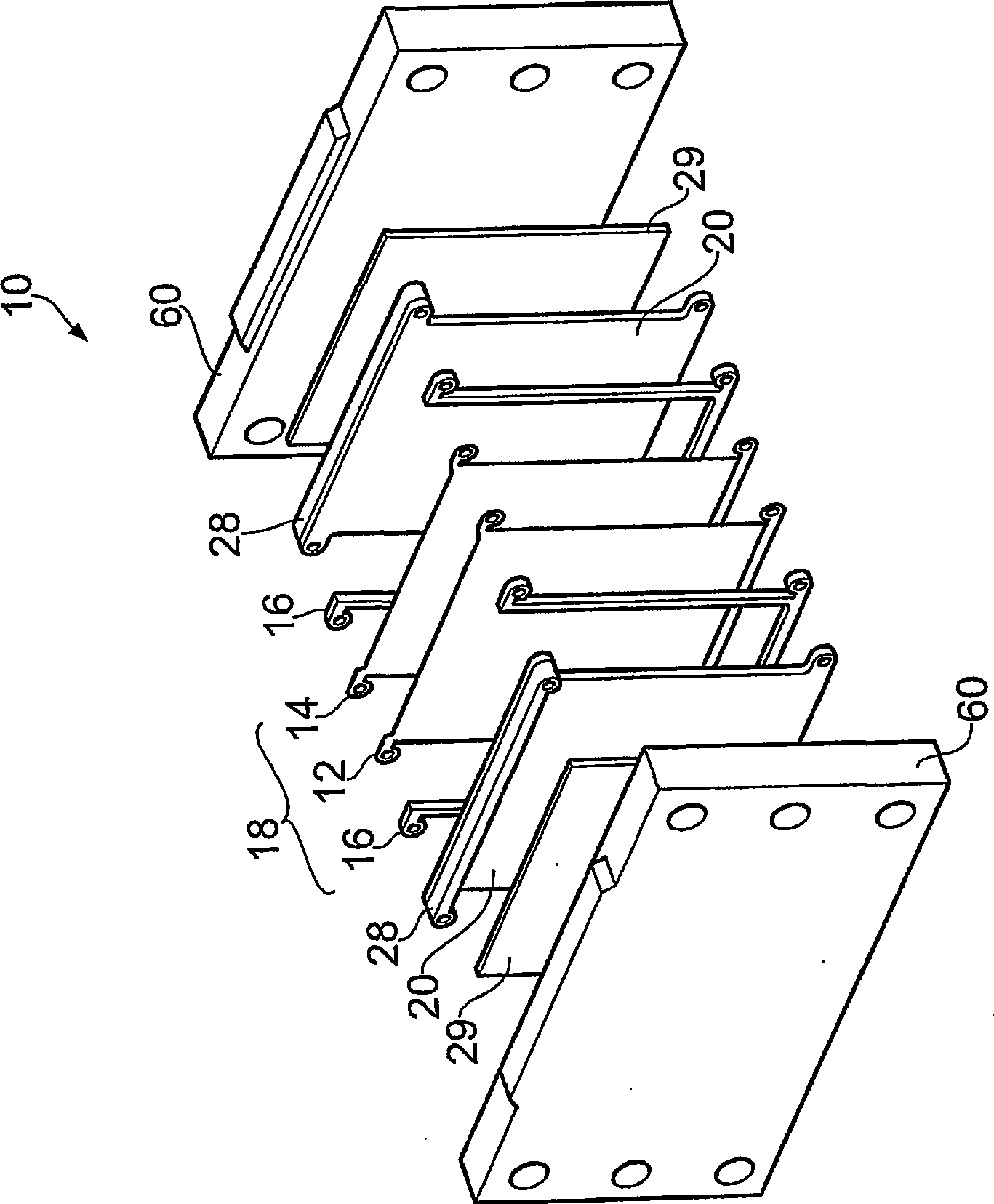
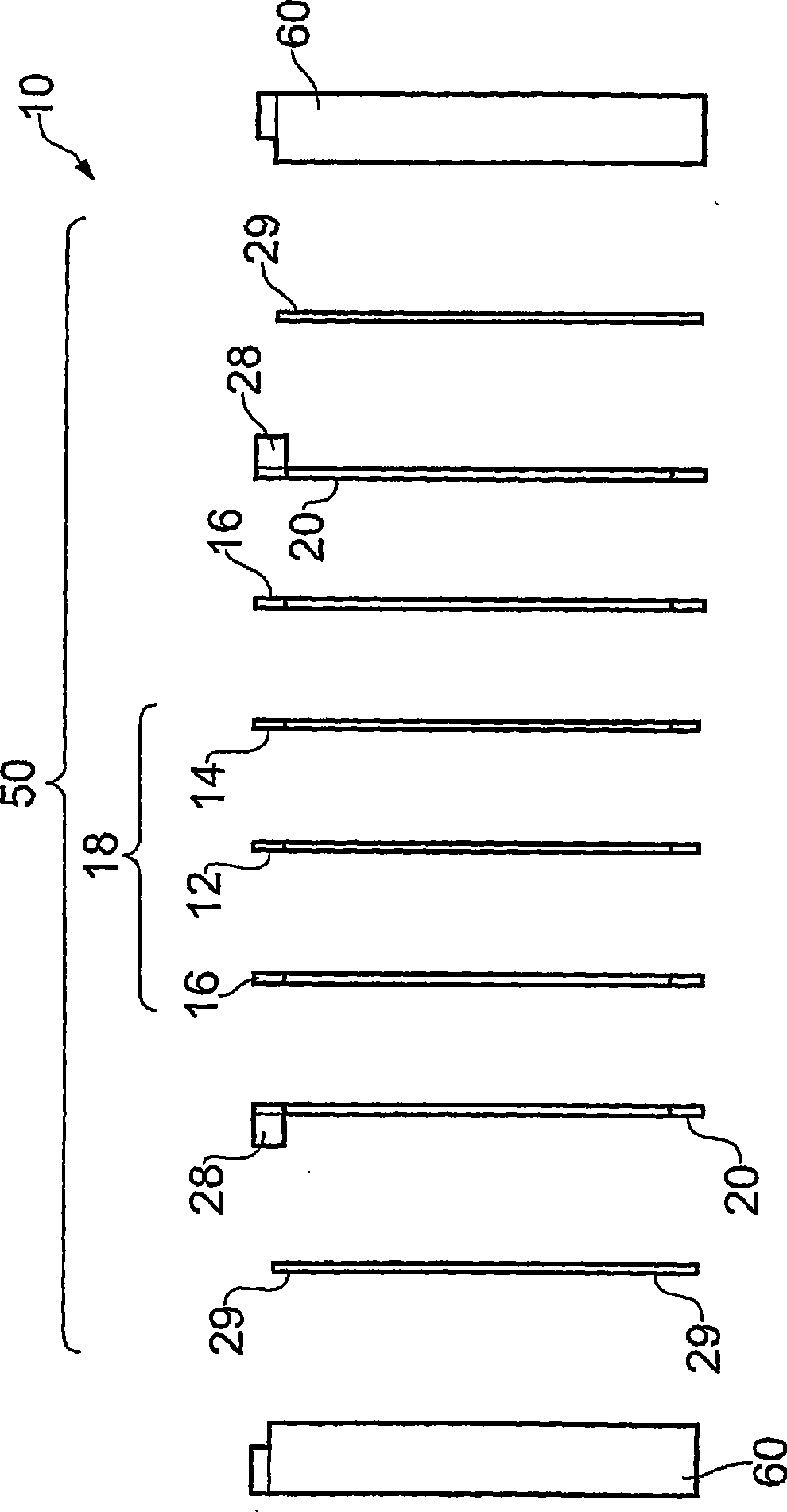
[0118] According to the first embodiment of the present invention, the plate heat exchanger 10 such as figure 1 (perspective view) and figure 2 (side view) settings shown.

[0119] The heat exchanger 10 comprises a 0.7 mm thick stainless steel etched plate element 12 sandwiched between a 0.1 mm thick stainless steel flat plate 14 and a 4 mm thick "U" shaped gasket 16 .

[0120] Spacer 16 is laser cut from stainless steel plate. The etched plate elements 12 , plate elements 14 and spacers 16 form a basic plate member unit 18 which is repeated several times along the length of the heat exchanger 10 . For clarity, in figure 1 and figure 2 Only a single unit 18 is shown in .

[0121] When the heat exchanger is used as a sorption generator, the gasket 16 is packed with activated carbon sorbent (not shown). Many of these repeating units 18 are nickel-copper welded together to form the complete exchanger 10 . When a sufficient number of units 18 (between 20 and 25 for most a...


PUM


Abstract

This invention relates to the field of heat-driven cooling devices, heat pumps or thermal transformers, in particular to those devices, known as sorption devices, which employ an ad- or absorbent material as a chemical compressor to raise the pressure of a refrigerant gas. This invention is particularly concerned with a heat exchanger suitable for use as a generator in a sorption device. Embodiments of the invention provide a heat exchanger comprising: a plurality of stacked plate members each plate member being provided with at least one fluid channel therein, each plate member having a channel inlet and a channel outlet associated with each channel of the plate member; a plurality of chambers, the chambers being provided between opposed major faces of respective adjacent plate members, the chambers containing a sorbent material; a thermal fluid inlet in communication with a plurality of the channel inlets and a thermal fluid outlet in communication with a plurality of the channel outlets; and a sorbate inlet and a sorbate outlet in communication with each of the chambers, the fluid channels being provided in fluid isolation from the chambers.

Description

technical field [0001] The present invention relates to the field of thermally driven cooling devices, heat pumps or thermal transformers, in particular those known as adsorption devices, which employ adsorbents or absorbent materials as chemical compressors to increase the pressure of refrigerant gases. The invention relates in particular to a heat exchanger suitable for use as a solid-gas reactor which will be referred to hereinafter as an adsorption device. Background technique [0002] Heat pumps, thermal transformers and cooling systems are generally based on the thermodynamics of condensation and evaporation of refrigerant gases. When a gas condenses into a liquid, heat is prevented from reaching the environment, and when the liquid evaporates, heat is absorbed. The evaporation / condensation cycle is driven by compression. If the selected environment comes into thermal contact with the gas / liquid eg only during the evaporation phase, then this environment experiences ...

Claims


Application Information

Patent Timeline
Patent Type & Authority Applications(China)
IPC IPC(8): F25B35/04
CPCY02B30/62F25B35/04Y02B30/64B60H1/32014Y02A30/27B01D53/04B60H1/3201F25B17/08F25B17/083F25B37/00F28D9/00F28F3/08Y02B30/00
Inventor R·克罗托夫
Owner UNIVERSITY OF WARWICK
Learn More