Timing measurement method, system and apparatus
A timing measurement and timing technology, applied in the field of mobile communication, can solve the problems of unstable timing measurement and large timing error, and achieve the effect of improving the performance of wireless positioning algorithm
- Summary
- Abstract
- Description
- Claims
- Application Information
AI Technical Summary
Problems solved by technology
Method used
Image
Examples
Embodiment 1
[0044] Embodiment 1. Process according to the processing threshold of the relevant power to obtain the first reliable path:
[0045] First, according to the existing implementation, the terminal obtains the relevant power according to the received signal obtained by analysis and the known transmitted signal: P(i)=|X(i)| 2 , i=1, 2, ..., L+N-1, wherein, X(i) is the shifted complex correlation signal obtained according to the received signal and the known transmitted signal, L is the length of the received signal, and N is The length of the sent signal.
[0046] The relevant power is affected by environmental factors and fading and contains some interference components. In order to remove these interference components, the following methods can be used in the calculation process:
[0047] For P(i), i=1, 2..., L+N-1, search for peak power P max , with Γ=P max *α is the power processing threshold, Γ is the threshold value, and α is the correction factor, which can be determined...
Embodiment 2
[0056] Embodiment 2. The method of obtaining the first reliable path according to the cumulative sum of related power:
[0057] First, according to the existing implementation, the terminal obtains the relevant power according to the received signal obtained by analysis and the known transmitted signal: P(i)=|X(i)| 2 , i=1, 2, ..., L+N-1, wherein, X(i) is the shifted complex correlation signal obtained according to the received signal and the known transmitted signal, L is the length of the received signal, and N is The length of the sent signal.
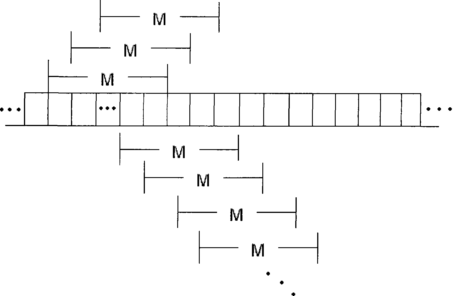
[0058] Calculate the cumulative power sum of the relevant power obtained by M consecutive calculations:
[0059] P cum sfn ( i ) = P ( i ) ...
Embodiment 3
[0067] Embodiment 3. According to the position of the maximum path of the received signal of the relevant power, the method of determining the first reliable path:
[0068] First, according to the existing implementation, the terminal obtains the relevant power according to the received signal obtained by analysis and the known transmitted signal: P(i)=|X(i)| 2 , i=1, 2,..., L+N-1, wherein, X(i) is the shifted complex correlation signal obtained according to the received signal and the known transmitted signal, L is the length of the received signal, and N is The length of the sent signal.
[0069] Similarly, because it is affected by environmental factors and contains some interference components, in order to remove these interference components, the following methods can be used in the calculation process:
[0070] Find the peak power P of P(i), i=1, 2..., L+N-1 max (i), determine the peak position i max . Then it is considered that the arrival time of the main path of t...
PUM
 Abstract
Description
Claims
Application Information
 - R&D Engineer
- R&D Manager
- IP Professional
- Industry Leading Data Capabilities
- Powerful AI technology
- Patent DNA Extraction
Browse by: Latest US Patents, China's latest patents, Technical Efficacy Thesaurus, Application Domain, Technology Topic, Popular Technical Reports.
© 2024 PatSnap. All rights reserved.Legal|Privacy policy|Modern Slavery Act Transparency Statement|Sitemap|About US| Contact US: help@patsnap.com


