
Up-conversion solar cell

A technology for solar cells and silicon solar cells, applied in the field of solar cells, can solve problems such as unfavorable large-area production, insufficient light absorption, complex structure, etc., and achieve the effects of reducing heat conversion, reducing consumption, and improving use efficiency

Inactive Publication Date: 2009-07-22
BEIJING JIAOTONG UNIV
View PDF0 Cites 16 Cited by
  • Summary
  • Abstract
  • Description
  • Claims
  • Application Information

AI Technical Summary

Problems solved by technology

There are still many problems in the above technology: firstly, the materials used cannot fully absorb the light in the mid-infrared band of sunlight; secondly, the structure is complicated and the cost is high, which is not conducive to large-scale production

Method used


Image

  • Up-conversion solar cell

Examples


Embodiment 1

[0014] An up-conversion solar cell whose structure is:

[0015] Directly on the backlight surface of the silicon solar cell 2, the nano upconversion luminescent material is erbium ion-doped silica-lanthanum fluoride nanocrystalline glass ceramics by spin coating to prepare the nano upconversion luminescent layer 3; It absorbs the sunlight transmitted by the silicon solar cell and emits the corresponding light absorbed by the silicon solar cell.

[0016] The thickness of the nanometer up-conversion light-emitting layer 3 is 0.5 micrometers.

Embodiment 2

[0018] An up-conversion solar cell 2, which is directly on the backlight surface of the silicon solar cell, using the method of screen printing, and the nano-upconversion luminescent material is erbium ion and ytterbium ion co-doped silicon dioxide-lanthanum fluoride nano Crystal glass ceramics prepare the nanometer up-conversion light-emitting layer 3.

[0019] The thickness of the nanometer up-conversion light-emitting layer 3 is 2 micrometers.

Embodiment 3

[0021] An up-conversion solar cell whose structure is:

[0022] Directly on the backlight surface of the silicon solar cell 2, the nano upconversion luminescent layer 3 is prepared using the nano upconversion luminescent material which is zinc sulfide doped with erbium ions by spin coating.

[0023] The thickness of the nanometer up-conversion light-emitting layer 3 is 1 micron.

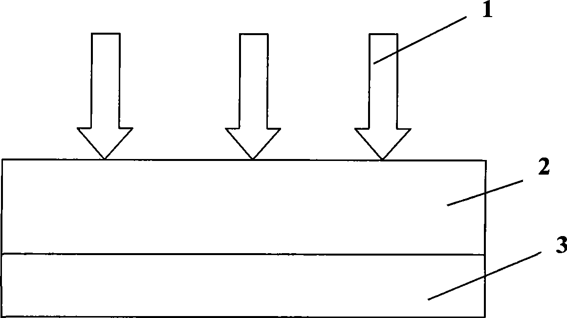
[0024] Such as figure 1 As shown, sunlight 1 is incident from the front of a silicon solar cell 2, and a nano-upconversion luminescent layer 3 made of nano-upconversion luminescent materials converts long-wavelength light that silicon cannot absorb into light that silicon can absorb, thereby enhancing silicon solar energy. The battery's utilization of long-wavelength sunlight.

[0025] Nano up-conversion luminescent material substances used in the present invention:

[0026] Erbium ion-doped silica-lanthanum fluoride nanocrystalline glass ceramics or erbium ion and ytterbium ion co-doped silica-lanthanum...


PUM

PropertyMeasurementUnit
Thicknessaaaaaaaaaa
Thicknessaaaaaaaaaa
Thicknessaaaaaaaaaa

Abstract

The invention discloses an up-conversion solar cell, relating to a solar cell. The up-conversion silicon solar cell is a nano up-conversion luminescence layer (3) prepared with nano up-conversion luminescent materials by the method of carrying out spin coating or screen printing on the back surface of the silicon solar cell (2); sunlight (1) comes in from the front of the silicon solar cell (2). The materials of the nano up-conversion luminescence layer (3) are silicon dioxide-lanthanum fluoride nanocrystalline glass ceramics doped with erbium ions, or silicon dioxide-lanthanum fluoride nanocrystalline glass ceramics doped with both erbium ions and ytterbium ions or zinc sulfide doped with erbium ions. The nano luminescence layer is 0.5-2um thick. The up-conversion silicon solar cell can convert the low-energy photons which can not be effectively absorbed by the silicon solar cells to the high-energy photons which the silicon solar cells can respond to, thus expanding the spectral response range of the solar cells, improving the service efficiency of sunlight in unit area and lowering the cost.

Description

Technical field [0001] The invention relates to a solar cell, which belongs to the technical field of energy. Background technique [0002] At present, the main reason for limiting the efficiency of solar cells is that solar cells cannot convert all sunlight into electric current. For silicon cells, the utilization rate of sunlight is about 55%, and only light with a wavelength less than 1.1um has enough energy to generate electron-hole pairs. Therefore, making full use of the sunlight spectrum is an effective way to improve the efficiency of solar cells. . For silicon cells, the utilization rate of sunlight is about 55%. In order to increase the utilization rate, Yoshihiro Hamakawa and Hideyuki Takakura of Kaneka, Japan, Key issues for the efficiency improvemenr of silicon basis stacked solar cells, 2000 IEEE, 766-771. The disclosed solar cell achieves an efficiency of 13.5% in an area of ​​91 cm×45 cm. Jeffrey Yang of United Solar, Arindam Banerjee, Recent progress in amorphous...

Claims


Application Information

Patent Timeline
IPC IPC(8): H01L31/055
CPCY02E10/50Y02E10/52
Inventor 赵谡玲徐征张福俊徐叙瑢
Owner BEIJING JIAOTONG UNIV
Learn More