Computer-aided design method for cam curve of three-component zooming system

A computer-aided, cam curve technology, applied in computing, special data processing applications, instruments, etc., can solve problems such as affecting the processing process of cams and cam curves, complicated calculations, and poor fusion system performance, etc. Excellent quality, good craftsmanship, and the effect of improving imaging quality

Active Publication Date: 2009-07-08
NANYANG LIDA PHOTOELECTRIC
View PDF0 Cites 4 Cited by
  • Summary
  • Abstract
  • Description
  • Claims
  • Application Information

AI Technical Summary

Problems solved by technology

Because the design of the cam and cam curve of the traditional zoom system is to use the interpolation method to roughly calculate the data of each point of the cam curve groove after correcting the aberration at several focal length positions, not only the calculation is cumbersome and complicated, but also there is still a certain amount of image plane drift At the same time, the position of the inflection point of the cam curve should be carefully checked and calculated, even relying on empirical values ​​for checking and processing, so as to ensure the smooth transition of the curve
In addition, the aberration design and cam design of the system are carried out in stages, which cannot be well integrated and conveniently evaluate system performance in real time, and will directly affect the processing process of the cam and cam curve

Method used


Image

  • Computer-aided design method for cam curve of three-component zooming system
  • Computer-aided design method for cam curve of three-component zooming system
  • Computer-aided design method for cam curve of three-component zooming system

Examples


Embodiment 1

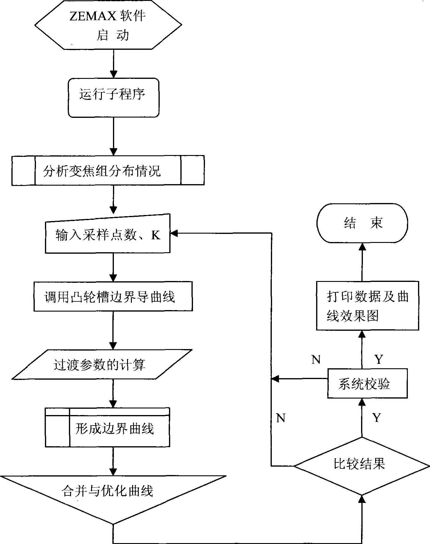
[0023] It is an embodiment of designing the cam curve of a three-component zoom lens for projection. The design method is: install ZEMAX optical design software on the computer used in the auxiliary design, and adjust the cam curve track according to the three-component optical system Based on the requirements of Gaussian optics and the macro language function of ZEMAX, compile the 3-CAM-ZPL program on the ZEMAX optical design software platform, run the program, and the program will automatically analyze the distribution of each zoom group of the three-component system, input Sampling points, calculate the transition parameters of the optical system, input the bending coefficient K of the second zoom group U2, calculate the zoom cam curve data by the 3-CAM.ZPL program, run the 3-CAM.ZPL program, and the program automatically judges each zoom group Whether interlacing occurs during the moving process, and a prompt message is output. If such a situation occurs, it means that the ...

Embodiment 2

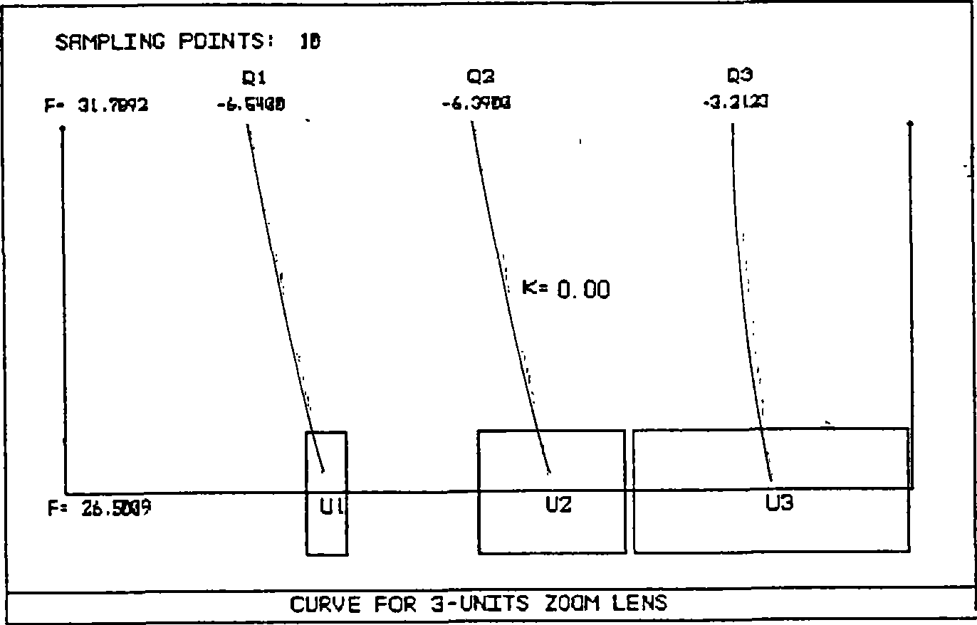
[0027] see Figure 4 , the steps of the design method are the same as in Embodiment 1. In this embodiment, the second zoom group U2 is selected to move in a curve (curved toward the object side), that is, K>0, and the number of sampling points is set to 10, and the 3-CAM.ZPL program is run to calculate The result is as follows:

[0028] K=0.03 Ave-MTF=0.6995 Max-AveMTF=0.7113 Min-AveMTF=0.6752

[0029] From the calculation data of Example 2, it can be seen that when K=0.03 of the second zoom group U2, that is, when the curve is slightly bent toward the object side, the value of Ave-MTF changes from 0.6842 when moving in a straight line to 0.6995, and the performance of the zoom system has seen an increase.

Embodiment 3

[0031] see Figure 5 , the steps of the design method are the same as in Embodiment 1. In this embodiment, the second zoom group U2 is selected to move in a curve (curved to the image plane), that is, K<0, the number of sampling points is set to 10, and the 3-CAM.ZPL program is run to calculate The result is as follows:

[0032] K=-0.05: Ave-MTF=0.6483 Max-AveMTF=0.7047 Min-AveMTF=0.6017

[0033] From the calculation data of Example 3, it can be seen that when K of the second zoom group U2=-0.05, that is, when the curve is slightly bent toward the image side, the value of Ave-MTF changes from 0.6842 when moving straight to 0.6483, and the zoom system Performance has been reduced.

[0034] from image 3 , Figure 4 , Figure 5 It can be seen that when the curvature coefficient K of the second zoom group U2 is different, the bending direction and degree of the curve of the third zoom group U3 are also different. When K=0, it means linear movement, K>0 means the curve bends t...


PUM


Abstract

The invention relates to a computer-aided design method for a cam curve in a three-component zooming system based on ZEMAX optical design software. According to requirements of a three-component optical system to the curve track of the cam, the Gauss optics principle is applied, the macro language function of the ZEMAX is adopted, and the 3-CAM-ZPL procedure is compiled, through the operation of the procedure, the number of sampling points of the cam curve and a curve coefficient K of moving track of a second zooming group are only input, that is, the value scope and the value quantity of the K value are automatically confirmed and comparatively analyzed through the 3-CAM-ZPL procedure, and the optimal design graphic of the cam curve can be obtained through adjusting the number of sampling points and the K value. The method can automatically generate and display graphics according to the design data of the cam curve, so that the design effect is intuitive, the modification is convenient, the design speed of the cam curve and the performance of products of cams are greatly improved, the development period of products is shortened, and the design cost is reduced.

Description

technical field [0001] The invention belongs to the technical field of computer-aided design, in particular to a computer-aided design method for a three-component zoom system cam curve used in an optical zoom system. Background technique [0002] With the continuous improvement of the performance requirements of the zoom optical system, higher and higher requirements are put forward for the design and processing of the zoom system and the matching cam curve. The cam curve design of the zoom system is a very important part in the post-design process of the zoom system. The quality of the curve design is directly related to the stability of the system image plane. A zoom system with excellent aberration design must be guaranteed by a stable cam curve design. Because the design of the cam and cam curve of the traditional zoom system is to use the interpolation method to roughly calculate the data of each point of the cam curve groove after correcting the aberration at several...

Claims


Application Information

Patent Timeline
Patent Type & Authority Applications(China)
IPC IPC(8): G06F17/50
Inventor 曹红曲马永珍王天洲
Owner NANYANG LIDA PHOTOELECTRIC
Why Eureka
Try Eureka