Circuit for detecting radio frequency power

A technology for detecting circuit and radio frequency power, applied in the direction of measuring electric power, measuring electric variables, electric vehicles, etc., can solve the problems of increasing the area of ​​​​the printed circuit board, the detection range is small, and the power detector detects the signal, etc., to save area, eliminate Limitation of forward voltage, effect of increasing range

Inactive Publication Date: 2009-07-08
RDA TECH
View PDF0 Cites 16 Cited by
  • Summary
  • Abstract
  • Description
  • Claims
  • Application Information

AI Technical Summary

Problems solved by technology

When the input power is too small and the diode is not turned on, the signal cannot be detected by the power detector
Therefore, using the existing method, the range of power detection is limited by the forward voltage of the rectifier diode, and the detection range is very small
If the power detection circuit is not integrated in the chip, a chip with power detection function needs to be added outside the power amplifier, thereby increasing the area of ​​the printed circuit board

Method used


Image

  • Circuit for detecting radio frequency power
  • Circuit for detecting radio frequency power
  • Circuit for detecting radio frequency power

Examples


Embodiment Construction

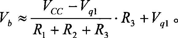
[0010] The circuit diagram of the radio frequency power detection circuit of the present invention is as figure 2 As shown, resistors R1, R2, R3 and a first diode are serially connected in series from the power supply terminal VCC to the ground, the cathode of the first diode is grounded, and the signal input terminal RF IN The capacitor C1 is connected to the node between the resistors R2 and R3, and this node is also connected to the base of the transistor Q2, and the collector of the transistor Q2 is connected to the node between the resistors R1 and R2, and the transistor Q2 A second diode and a resistor R4 are serially connected in series between the emitter of the transistor Q2 and the resistor R4, the cathode of the second diode is connected to the resistor R4, and the emitter of the triode Q2 is connected to the signal output terminal V OUT Resistors R5 and R7 are connected in series in sequence, a capacitor C2 is connected between the node between the resistors R7 an...


PUM


Abstract

The invention discloses a radiofrequency power detection circuit. A resistor R1, a resistor R2, a resistor R3 and a first diode are orderly and serially connected between a power end VCC and the ground, a signal input end RFIN is connected to a node between the resistor R2 and the resistor R3 through a capacitor C1, the node is also connected with a base electrode of a triode Q2, a collector of the triode Q2 is connected to a node between the resistor R1 and the resistor R2, a second diode and a resistor R4 are orderly and serially connected between an emitter of the triode Q2 and the ground, a resistor R5 and a resistor R7 are orderly and serially connected between the emitter of the triode Q2 and a signal output end VOUT, a capacitor C2 is connected between a node (between the resistor R7 and the resistor R5) and the ground, and a resistor RL is connected between the signal output end VOUT and the ground. The radiofrequency power detection circuit sets a direct current operating point of a radiofrequency power detector, eliminates the limit of positive voltage of a rectifier diode, and increases the range of radiofrequency power detection; and the detection circuit can be integrated into an HBT power amplification chip, which reduces peripheral elements of a power amplifier and saves the area of a printed circuit board.

Description

technical field [0001] The invention relates to a detection circuit, in particular to a radio frequency power detection circuit. Background technique [0002] In modern wireless communication systems, the RF power detector is one of the necessary circuits to realize the safe and stable operation of the system. The main function of the RF power detector, as the name implies, is to accurately detect the power at the transmit output end and enable the system to be precisely controlled. Therefore, the RF power detector needs to have a larger power detection range, including a wider input power detection range and input signal frequency range. Since the RF power detector is usually directly connected to the output end of the RF power amplifier, its influence on the output characteristics of the RF power amplifier should be minimized. [0003] At present, the radio frequency power amplifier mostly adopts the HBT (Heterojunction Bipolar Transistor, heterojunction transistor) proc...

Claims


Application Information

Patent Timeline
Patent Type & Authority Applications(China)
IPC IPC(8): G01R21/00
Inventor 陈俊袁志鹏
Owner RDA TECH
Why Eureka
Try Eureka