
Chemical mechanical grinding method and wafer cleaning method

A technology of chemical machinery and grinding method, which is applied in the direction of chemical instruments and methods, cleaning methods and utensils, cleaning methods using liquids, etc. It can solve the problem of easily remaining abrasive particles on the wafer, reduce the number of particle defects, and improve the repair quality Effect

Active Publication Date: 2009-06-17
SEMICON MFG INT (SHANGHAI) CORP
View PDF1 Cites 11 Cited by
  • Summary
  • Abstract
  • Description
  • Claims
  • Application Information

AI Technical Summary

Problems solved by technology

[0014] The invention provides a chemical mechanical grinding method and a wafer cleaning method to improve the existing phenomenon that some grinding particles are still easy to remain after cleaning the wafer after grinding the metal layer

Method used


Image

  • Chemical mechanical grinding method and wafer cleaning method
  • Chemical mechanical grinding method and wafer cleaning method
  • Chemical mechanical grinding method and wafer cleaning method

Examples


no. 1 example

[0066] This example introduces a new method of planarizing a metal layer by using a chemical mechanical polishing process. The metal layer can be metal copper or metal tungsten or the like.

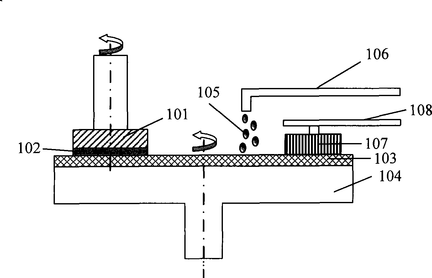
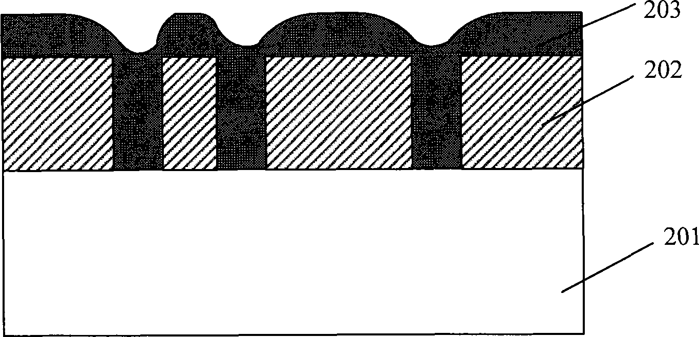
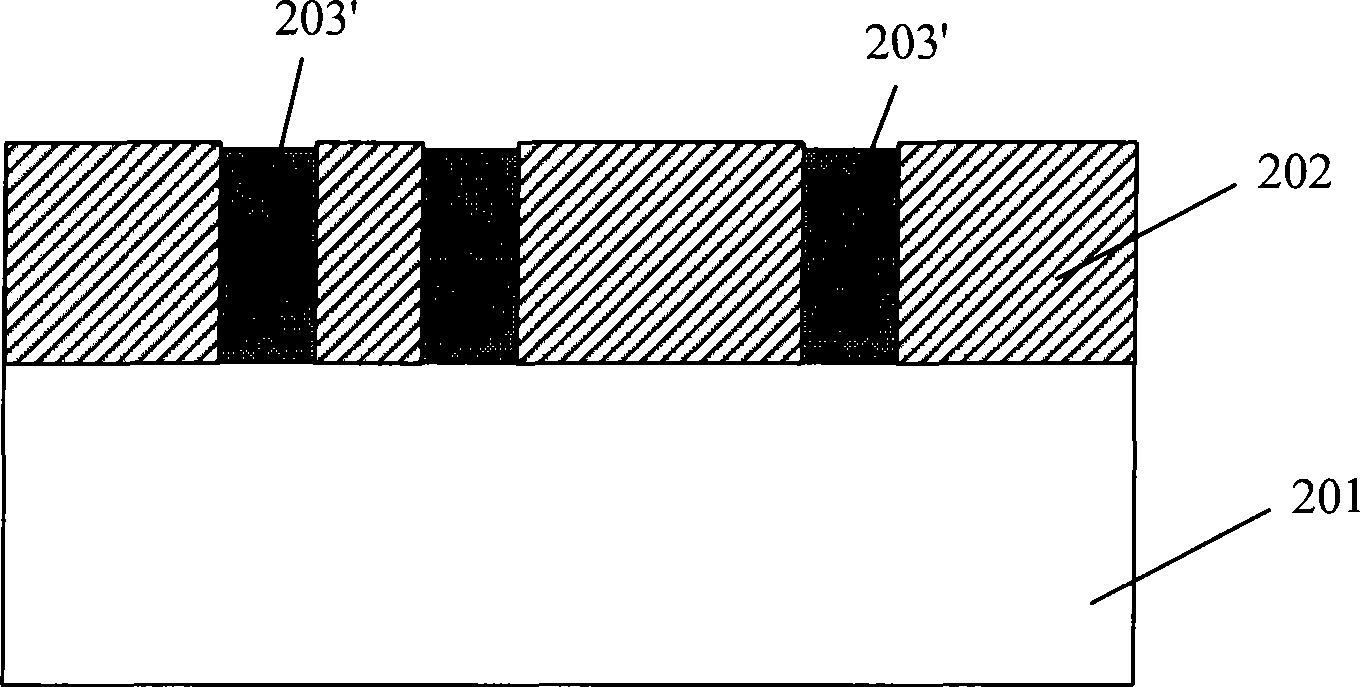
[0067] Image 6 It is a flowchart of the chemical mechanical polishing method in the first embodiment of the present invention, Figure 7 to Figure 11 In order to illustrate the device cross-sectional view of the first embodiment of the present invention, below in conjunction with Figure 6 to Figure 11 The first embodiment of the present invention will be described in detail.

[0068] Step 601: Place the wafer to be polished in chemical mechanical polishing equipment, and the dielectric layer, the through-hole opening in the dielectric layer, and the through-hole opening and on the dielectric layer have been formed on the wafer metal layer.

[0069] Figure 7 It is a schematic cross-sectional view of the device before the chemical mechanical polishing method is used to planarize the...

no. 2 example

[0102] The present invention also correspondingly provides a wafer cleaning method after grinding. Figure 12 It is the flowchart of the wafer cleaning method in the second embodiment of the present invention, below in conjunction with Figure 12 The second embodiment of the present invention will be described in detail.

[0103] The wafer cleaning method in the present embodiment comprises steps:

[0104] Step 1201: Provide a ground wafer, and the wafer has a dielectric layer, a via opening located in the dielectric layer, and a metal structure located in the via opening, and the metal structure is higher than the medium layer.

[0105] The ground wafer provided in this embodiment is as Figure 9 As shown, the substrate 701 may be a substrate on which metal oxide semiconductor transistors have been formed, or may be a substrate on which an underlying metal wiring structure has been formed. The dielectric layer 702 formed on the substrate 701 may be a silicon oxide layer f...


PUM


Abstract

The invention discloses a method of chemical mechanical polishing, which comprises steps of placing a chip to-be-polished on a chemical mechanical polishing device, wherein a dielectric layer, a through hole opening arranged in the dielectric layer, and a metal layer arranged in the through hole and on the dielectric layer are formed on the chip, performing first polishing on the chip to expose the surface of the chip out of the dielectric layer and form a metal structure in the through hole opening, performing second polishing on the chip to lead the metal structure in the through hole opening to be higher than the dielectric layer, mixing de-ionized water with hydrofluoric acid to form hydrofluoric acid solution of concentration ranging from 0.03% to 0.08%, and finally utilizing the hydrofluoric acid solution to clean the polished chip. The invention further correspondingly discloses a cleaning method for polished chips. By utilizing the mechanical polishing method and the chip cleaning method, defected particle number on the chip surface after the metal layer is polished can be effectively reduced.

Description

technical field [0001] The invention relates to the technical field of semiconductor manufacturing, in particular to a chemical mechanical polishing method and a wafer cleaning method. Background technique [0002] With the rapid development of ULSI (Ultra Large Scale Integration), the manufacturing process of integrated circuits has become more and more complex and refined, and the requirements for the flatness of the wafer surface have become more and more stringent. However, the multi-layer wiring technology widely used now will cause the surface of the chip to be uneven, which is extremely unfavorable for graphics production. For this reason, it is necessary to planarize the wafer so that each layer has a high global planarity. At present, chemical mechanical polishing (CMP) is the best method to achieve global planarization, especially after the semiconductor manufacturing process enters the sub-micron field, chemical mechanical polishing has become an indispensable M...

Claims


Application Information

Patent Timeline
IPC IPC(8): H01L21/768H01L21/00B08B3/08
Inventor 李健李福洪
Owner SEMICON MFG INT (SHANGHAI) CORP
Learn More