
Fixation joint part dynamics parameter identification method for machine tool

A technology of dynamic parameters and identification methods, applied in scientific instruments, mechanical devices, instruments, etc., can solve the problems of lack of universality, neglect of coupling characteristics, and lack of consideration of tangential mechanical characteristics of joints, etc. Identify the effects of high accuracy and rich dynamics

Inactive Publication Date: 2009-06-17
HUAZHONG UNIV OF SCI & TECH
View PDF0 Cites 17 Cited by
  • Summary
  • Abstract
  • Description
  • Claims
  • Application Information

AI Technical Summary

Problems solved by technology

[0005] 1) The joint parameters identified by modeling with this method are only applicable to a specific structure. When the size and shape of the joint change, it is difficult to transplant the joint surface parameters and is not universal
[0006] 2) In this model, only the stiffness characteristics and damping characteristics of the normal direction of each degree of freedom are considered, while the coupling characteristics between each degree of freedom are ignored, and the mechanical characteristics of the tangential direction of the joint are not considered
However, no matter which method, when identifying the parameters of the joint, it is only to test the frequency response function of each substructure, and there is no characteristic parameter of the joint (such as normal preload, surface roughness, metal material, surface processing method, etc.)
Therefore, no matter how accurate the identified parameters are, they can only be applied to the power system being identified and have no universal applicability

Method used


Image

  • Fixation joint part dynamics parameter identification method for machine tool
  • Fixation joint part dynamics parameter identification method for machine tool
  • Fixation joint part dynamics parameter identification method for machine tool

Examples


Embodiment Construction

[0031] Concrete implementation steps of the present invention are as follows:

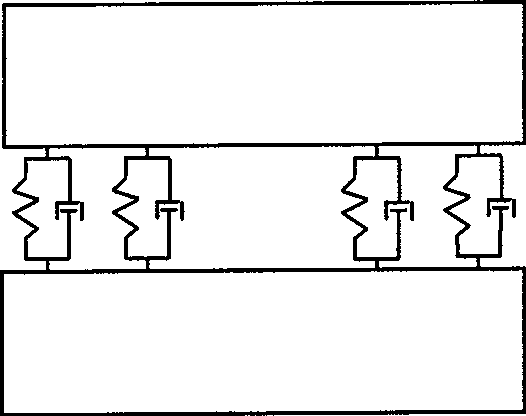
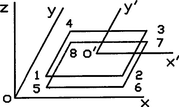
[0032] 1) Investigate the various forms of fixed joints of common machine tools, give the division criteria of the finite element model of the fixed joint, extract its essential properties, and establish a "parametric" joint dynamics model;

[0033] 2) Perform finite element analysis on the substructure and extract the substructure mass matrix M 0 and the stiffness matrix K 0 , the substructure is generally made of steel, and the material damping of this material itself is very small. In this case, 90% of the internal damping of the machine tool structure comes from the joint of the machine tool, so the damping matrix of the substructure C 0 Combined with the damping matrix C 1 negligible compared to

[0034] 3) According to the node correspondence of the "parameterized" joint element dynamic model, using the finite element matrix assembly theory, the substructure stiffness matrix K 0 and the ...


PUM


Abstract

The invention provides an identification method of dynamic parameters of a machine tool fixed joint part. The method comprises the following steps: taking a structural damping matrix of a joint part unit and a stiffness matrix of the joint part unit as parametric variables, setting the difference between the product of a displacement impedance matrix and a displacement frequency response function and a unit matrix to be minimum as an optimum design objective, and obtaining parameter variable values (i.e., the identified parameters of the joint part) through multiple iteration. The identification method takes damping and stiffness of multiple key freedom directions and the intercoupling relation into account to avoid a secondary error produced by matrix inversion, has high precision, and more accurately characterizes richer dynamic characteristics of the joint part.

Description

technical field [0001] The invention relates to a method for identifying dynamic parameters of common fixed joints (bolt joints) of machine tools, in particular to a method for identifying stiffness and damping parameters of the joint. Background technique [0002] Since the 1960s, when people realized the important influence of joints in machine tool structures on the overall machine structure, researchers have conducted extensive and in-depth research on the dynamic characteristics of joints and parameter identification methods, and have achieved remarkable results. the results. However, the property parameters of the junction cannot be precisely controlled, so there are still many problems to be further studied. [0003] It is an indisputable fact that no matter what type of junction, its junction belongs to "flexible junction". The so-called "flexible joint" means that when the joint is subjected to an external complex dynamic load, there will be a multi-degree-of-free...

Claims


Application Information

Patent Timeline
Patent Type & Authority Applications(China)
IPC IPC(8): G01N19/00G01N3/00G01M19/00
Inventor 毛宽民李斌徐强
Owner HUAZHONG UNIV OF SCI & TECH
Learn More