
Wheel self-powered broadband energy collector

An energy harvester, self-powered technology, applied in electrical components, generators/motors, piezoelectric effect/electrostrictive or magnetostrictive motors, etc., can solve environmental pollution of chemical batteries, large volume energy collection efficiency, etc. question

Active Publication Date: 2021-05-11
TIANJIN POLYTECHNIC UNIV
View PDF3 Cites 0 Cited by
  • Summary
  • Abstract
  • Description
  • Claims
  • Application Information

AI Technical Summary

Problems solved by technology

[0002] With the emergence of various new radio components, how to supply power for low-power radio products has become the focus of attention. For example, the interior of shared bicycles needs to supply power to warning lights, lighting and positioning systems. The commonly used power supply method is solar power, and when When riding at night or in a rainy environment for a long time, other methods of power supply are also required. The commonly used chemical batteries need to be replaced regularly and will pollute the environment. Therefore, how to convert the energy in the surrounding environment into electrical energy and provide low power New Energy Harvesters Powered by Wireless Products Become a Research Hotspot
Under the existing technical conditions, the piezoelectric vibration energy harvester uses the positive piezoelectric effect to convert the vibration energy in the environment into electrical energy, does not need an external power supply, and has no pollution to the environment, but it has a large volume and needs further improvement in energy harvesting efficiency. raised questions

Method used


Image

  • Wheel self-powered broadband energy collector
  • Wheel self-powered broadband energy collector
  • Wheel self-powered broadband energy collector

Examples


Embodiment Construction

[0032] It should be noted that, in the case of no conflict, the embodiments of the present invention and the features in the embodiments can be combined with each other.

[0033] In describing the present invention, it should be understood that the terms "center", "longitudinal", "transverse", "upper", "lower", "front", "rear", "left", "right", " The orientations or positional relationships indicated by "vertical", "horizontal", "top", "bottom", "inner" and "outer" are based on the orientations or positional relationships shown in the drawings, and are only for the convenience of describing the present invention and Simplified descriptions, rather than indicating or implying that the device or element referred to must have a particular orientation, be constructed and operate in a particular orientation, and thus should not be construed as limiting the invention. In addition, the terms "first", "second", etc. are used for descriptive purposes only, and should not be understood ...


PUM


Abstract

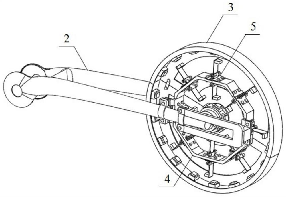
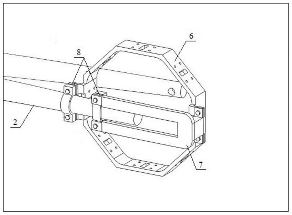
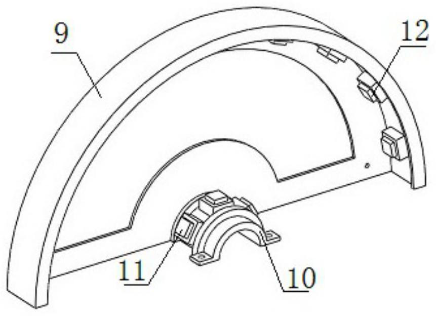
The invention provides a wheel self-powered broadband energy collector. The wheel self-powered broadband energy collector comprises a rotating support assembly and a fixed support assembly. The rotating support assembly comprises two rotating support semi-rings, and the two rotating support semi-rings are fixedly arranged on a rotating shaft of a wheel in a clamping mode to form a circle. A plurality of inner magnets are arranged at the circle center positions of the two rotating support semi-rings, and a plurality of outer magnets are arranged at the edge positions of the two rotating support semi-rings. The fixing support assembly comprises a piezoelectric beam fixing frame, and the piezoelectric beam fixing frame is fixedly connected with a vehicle frame. A plurality of piezoelectric beam assemblies are arranged on the piezoelectric beam fixing frame at equal intervals. According to the wheel self-powered broadband energy collector, through the innovative structural design, the size of the collector can be effectively reduced, and the energy collection efficiency of the collector is improved.

Description

technical field [0001] The invention belongs to the field of energy collectors, in particular to a wheel self-powered broadband energy collector. Background technique [0002] With the emergence of various new radio components, how to supply power for low-power radio products has become the focus of attention. For example, the interior of shared bicycles needs to supply power to warning lights, lighting and positioning systems. The commonly used power supply method is solar power, and when When riding at night or in a rainy environment for a long time, other methods of power supply are also required. The commonly used chemical batteries need to be replaced regularly and will pollute the environment. Therefore, how to convert the energy in the surrounding environment into electrical energy and provide low power A new type of energy harvester that consumes power from radio products has become a research hotspot. Under the existing technical conditions, the piezoelectric vibra...

Claims


Application Information

Patent Timeline
Patent Type & Authority Applications(China)
IPC IPC(8): H02N2/18
CPCH02N2/186
Inventor 姚明辉刘鹏飞牛燕吴启亮
Owner TIANJIN POLYTECHNIC UNIV
Learn More