
Forward gain estimating system suitable for complete-digital closed-loop optical fiber gyroscope

A fiber optic gyroscope, all-digital technology, applied in Sagnac effect gyroscopes, measuring devices, instruments, etc., can solve problems such as no light, fiber optic gyroscope entering dead zone, and fiber optic gyroscope detection signal-to-noise ratio reduction. handy effect

Inactive Publication Date: 2009-06-17
BEIHANG UNIV
View PDF0 Cites 12 Cited by
  • Summary
  • Abstract
  • Description
  • Claims
  • Application Information

AI Technical Summary

Problems solved by technology

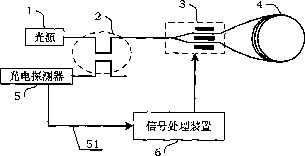
Space γ-rays have the most serious impact on the fiber ring 4, which will cause the optical transmission characteristics of the optical fiber to deteriorate, or even not pass through the light; the high-power fiber optic light source 1 is also easily affected by γ-rays due to the doping of erbium fibers, resulting in the output of the light source 1. fiber power decreases; the photodetector 5 is impacted by high-energy protons in space, and the photoelectric responsivity will decrease; the above-mentioned effects will reduce the signal-to-noise ratio of the fiber optic gyroscope, and the random walk error of the gyroscope will increase, and the random walk error will increase. Affect the accuracy of satellite navigation and attitude positioning
[0004] The angular velocity sensitive to the fiber optic gyro on the satellite is very small, and it may often work near zero angular velocity. In this case, the size of the forward gain is closely related to the dead zone of the fiber optic gyro. If the optical power signal received by the photodetector 5 51 (useful signal) is less than the ladder wave signal 651, the fiber optic gyro enters the dead zone, which seriously affects the application of the fiber optic gyro on satellites

Method used


Image

  • Forward gain estimating system suitable for complete-digital closed-loop optical fiber gyroscope
  • Forward gain estimating system suitable for complete-digital closed-loop optical fiber gyroscope
  • Forward gain estimating system suitable for complete-digital closed-loop optical fiber gyroscope

Examples


Embodiment Construction

[0027] The present invention will be further described in detail below in conjunction with the accompanying drawings and embodiments.

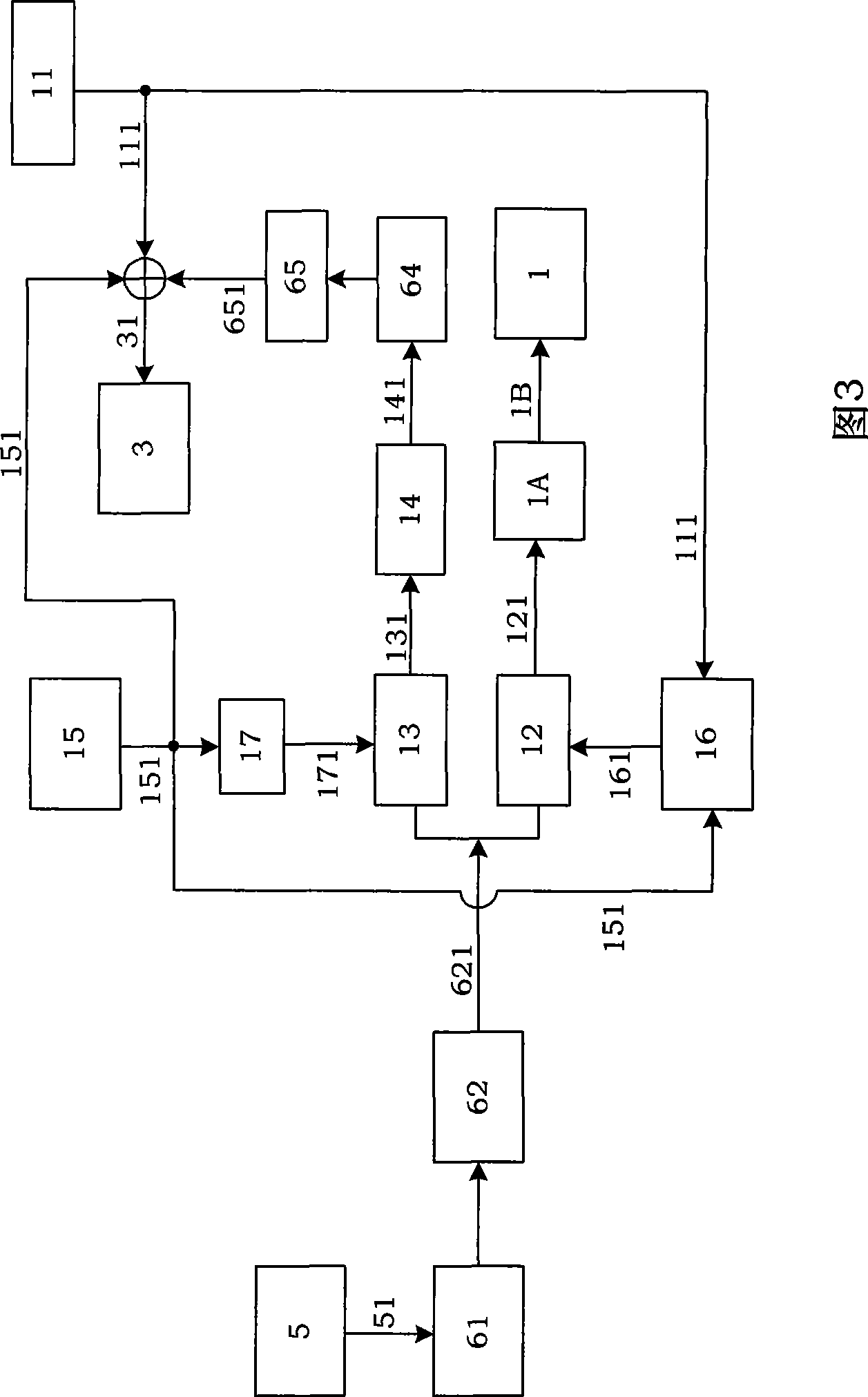
[0028] Referring to shown in Fig. 3, the present invention is a kind of forward gain estimation system applicable to full digital closed-loop fiber optic gyroscope, this forward gain estimation system adopts Verilog HDL language to write and realize in FPGA chip, and this FPGA chip is full digital closed loop optical fiber The main CPU of the gyro. The present invention uses the pseudo-random disturbance identification method to estimate the forward gain online, and superimposes the pseudo-random signal 111 and the square wave modulation signal 151 on the feedback ladder wave signal 651 as the identification input signal 31 of the integrated optical modulator 3; The strong voltage signal 621 undergoes pseudo-random demodulation while performing square wave demodulation, and extracts the value of the forward gain in real time.

[0029] The opt...


PUM


Abstract

The invention discloses a forward gain assessment system applicable to a full digital closed loop optical fibre gyro. In FPGA chip, the forward gain assessment system is realized by Verilog HDL, the FPGA chip is the central processor of the full digital closed loop optical fibre gyro. On-line assessment is carried out on the forward gain by adopting a pseudo-random perturbation identification method; a pseudo-random signal (111) and a square wave modulation signal (151) are overlaid on a fedback step wave signal (651) to be used as an identification input signal (31) of an integrated-optic modulator; a digital optical intensity voltage signal (621) demodulates the square wave during pseudorandom demodulation, so as to extract the value of the forward gain in real time. The forward gain assessment system can carry out on-line assessment under the normal operation of the full digital closed loop optical fibre gyro and monitor the effect brought about by the signal-to-noise ratio of the gyro and a dead area nonlinear effect in real time.

Description

technical field [0001] The present invention relates to a kind of forward gain estimation, more particularly, refers to a method of pseudo-random disturbance identification method for estimating the forward gain of all-digital closed-loop fiber optic gyroscope. Background technique [0002] The fiber optic gyroscope is an instrument for measuring angular velocity, and its hardware includes a light source 1, a coupler 2, an integrated optical modulator 3, an optical fiber ring 4, a photodetector 5 and a signal processing device 6 (see figure 1 shown). The signal processing device 6 includes a preamplifier circuit 61 for detecting the optical power signal 51 output by the photodetector 5, an A / D converter 62, a central processing unit 63, a D / A converter 64 and an amplification conditioning circuit 65 components (see Figure 2). With the development of electronic technology, the central processor 63 often adopts a DSP processor chip, or an FPGA processor chip, or a dual-proce...

Claims


Application Information

Patent Timeline
IPC IPC(8): G01C25/00G01C19/64
Inventor 李敏宋凝芳李洪全杨德钊袁锐林松陈婧
Owner BEIHANG UNIV
Learn More