Non-contact electronic throttle angle sensor for automobile

An angle sensor and automotive electronics technology, applied in the direction of instruments, electrical control, and electrical devices, can solve the problems of easy wear, interference with ECU working status, poor reliability, etc., and achieve the effect of precise positioning

Inactive Publication Date: 2009-06-10
肇庆市声光电子器材有限公司 +2
View PDF0 Cites 10 Cited by
  • Summary
  • Abstract
  • Description
  • Claims
  • Application Information

AI Technical Summary

Problems solved by technology

In the early days, the potentiometer here was a sliding resistance type, which has many disadvantages, because it has contact points, is easy to wear (rotation life: about 3 million times), poor reliability, and the occasional electric spark will interfere with the ECU. Working status (thus burying potential safety hazards) and many other shortcomings

Method used


Image

  • Non-contact electronic throttle angle sensor for automobile
  • Non-contact electronic throttle angle sensor for automobile
  • Non-contact electronic throttle angle sensor for automobile

Examples


Embodiment 1

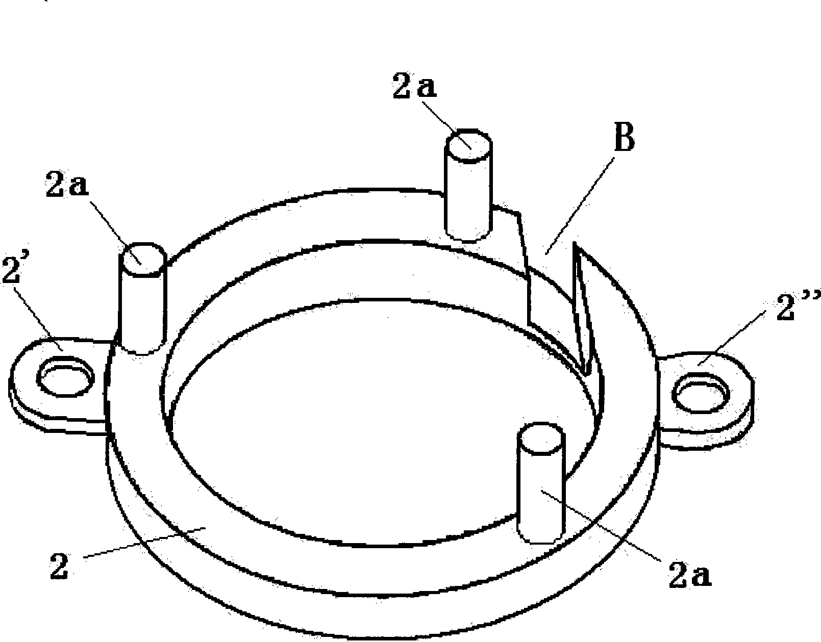
[0019] Embodiment 1, combining image 3 , in the figure: 2 is the positioning pressure ring, 2' and 2" are the earrings, the earrings 2' and 2" are integrated with the positioning pressure ring 2, the earrings 2' and 2" are on the side of the positioning pressure ring 2, the earrings 2' and 2" is used to fix the positioning pressure ring 2. 2a is a foot. The foot 2a is integrated with the positioning pressure ring 2. The foot 2a is on the bottom surface of the positioning pressure ring 2. The foot 2a is used for precise positioning of the positioning pressure ring 2. The foot 2a is cylindrical Either a square column or a triangular column, the bottom of the foot 2a is a plane or spherical or conical surface, B is a groove, the groove B is on the bottom surface of the positioning pressure ring 2, and the groove B is used to limit one end of the spring 7 7a.

[0020] combine Figure 4 , in the figure: 7 is the spring, 7a and 7b are the two ends of the spring 7 respectively.

...

Embodiment 2

[0022] Example 2, combined with Figure 6 , in the figure: 2 is the positioning pressure ring, 2a is the foot, the difference between embodiment 1 and embodiment 2 is that the foot 2a on the positioning pressure ring 2 in embodiment 1 is cylindrical or square column or triangular column Shaped column, and the foot 2a on the positioning pressure ring 2 among the embodiment 2 is the wave chain type flat-bottomed shape foot.

Embodiment 3

[0023] Example 3, combined with Figure 7 , in the figure: 2 is the positioning pressure ring, 2a is the foot, the difference between embodiment 1 and embodiment 2 and embodiment 3 is: the foot 2a on the positioning pressure ring 2 in embodiment 1 is cylindrical or square column Shaped or triangular column, the pin 2a on the positioning pressure ring 2 in embodiment 2 is a wave chain type flat-bottomed foot, and the pin 2a on the positioning pressure ring 2 in embodiment 3 is a wave chain type arc bottom shape foot.


PUM


Abstract

The invention relates to a non-contact automobile electron accelerator angle sensor, in particular to an automobile electron accelerator angle sensor which arranges a positioning pressing ring and a transverse bolt inside the traditional magnetosensitive non-contact angle sensor so as to realize the accurate positioning. The non-contact automobile electron accelerator angle sensor comprises a sensor body, a rotating shaft, the positioning pressing ring, a magnet, the transverse bolt, epoxide resin, a spring, a circuit board and a sensing unit mounted on the surface of the circuit board. The basic principle of the non-contact automobile electron accelerator angle sensor is that: when the automobile accelerator pedal drives the rotary magnet to rotate in a non-contact way above the sensing unit, magnetic lines are cut by magneto sensors in the sensing unit to induce the changing voltage signal, and the linear voltage signal is output after being processed by the microprocessor and the digital signal processing circuit which are integrated in advance in the sensing unit. The linear voltage signal is used for changing the working condition of the automobile engine. The interior installation of the non-contact automobile electron accelerator angle sensor of the invention greatly improves the accuracy and the reliability of the magnetosensitive non-contact angle sensor, and prolongs the service life thereof.

Description

(1) Technical field [0001] The present invention relates to a non-contact automotive electronic throttle angle sensor, in particular to a precisely positioned non-contact automotive electronic throttle angle sensor. An automotive electronic throttle angle sensor with a ring and a horizontal pin. (2) Background technology [0002] As we all know, in the running of a car, the traditional engine control mechanism works through a cable (soft steel wire) or a pull rod, one end of which is connected to the accelerator pedal, and the other end is connected to the throttle linkage plate. However, the scope of application of this traditional throttle is limited and lacks precision. Under the ever-changing development of automotive electronics technology, electronic throttle has emerged as the times require. After the engine of the car using the electronic accelerator is started, the accelerator pedal is in a fully relaxed state. When the driver starts to step on the electronic accel...

Claims


Application Information

Patent Timeline
Patent Type & Authority Applications(China)
IPC IPC(8): G01B7/30F02D41/00
Inventor 黄荟伍国伟
Owner 肇庆市声光电子器材有限公司
Why Eureka
Try Eureka