Work clamp and wire bonding device

A technology for wire bonding devices and workpiece fixtures, applied in auxiliary devices, manufacturing tools, electrical components, etc., can solve the problems of insufficient nitrogen gas, insufficient inhibition of oxidation of the bonding area, and increase in bonding costs, and achieve the effect of inhibiting oxidation.

Active Publication Date: 2009-05-06
KAIJOO KK
View PDF1 Cites 4 Cited by
  • Summary
  • Abstract
  • Description
  • Claims
  • Application Information

AI Technical Summary

Problems solved by technology

[0008] However, in the above-mentioned conventional work holder, the nitrogen gas introduced from the gas inlet 26 is once discharged into the hollow space 28, and then introduced into the chamber 22 through the conduit 24 from the hollow space 28. Therefore, although the oxidation of the joint area is prevented, it cannot Introducing a sufficient amount of nitrogen into chamber 22
That is, since the end of the hollow space 28 is connected to the atmosphere, most of the nitrogen gas flowing into the hollow space 28 is discharged to the atmosphere from the end, so that the amount of nitrogen gas introduced into the chamber 22 through the conduit 24 becomes insufficient.
As a result, the oxidation of the junction area cannot be sufficiently suppressed
[0009] In addition, in the hollow space 28, the nitrogen flow injected once to the lead frame 12 is directed to the conduit 24, the chamber 22 and the opening 17, so as to prevent the bonding area Oxidation, therefore, the use of nitrogen gas increases, resulting in increased bonding costs
In addition, in the above-mentioned conventional work holder, even if a large amount of nitrogen gas is used, the oxidation of the joint region cannot be sufficiently suppressed.

Method used


Image

  • Work clamp and wire bonding device
  • Work clamp and wire bonding device
  • Work clamp and wire bonding device

Examples


Embodiment Construction

[0040] Hereinafter, embodiments of the present invention will be described with reference to the drawings.

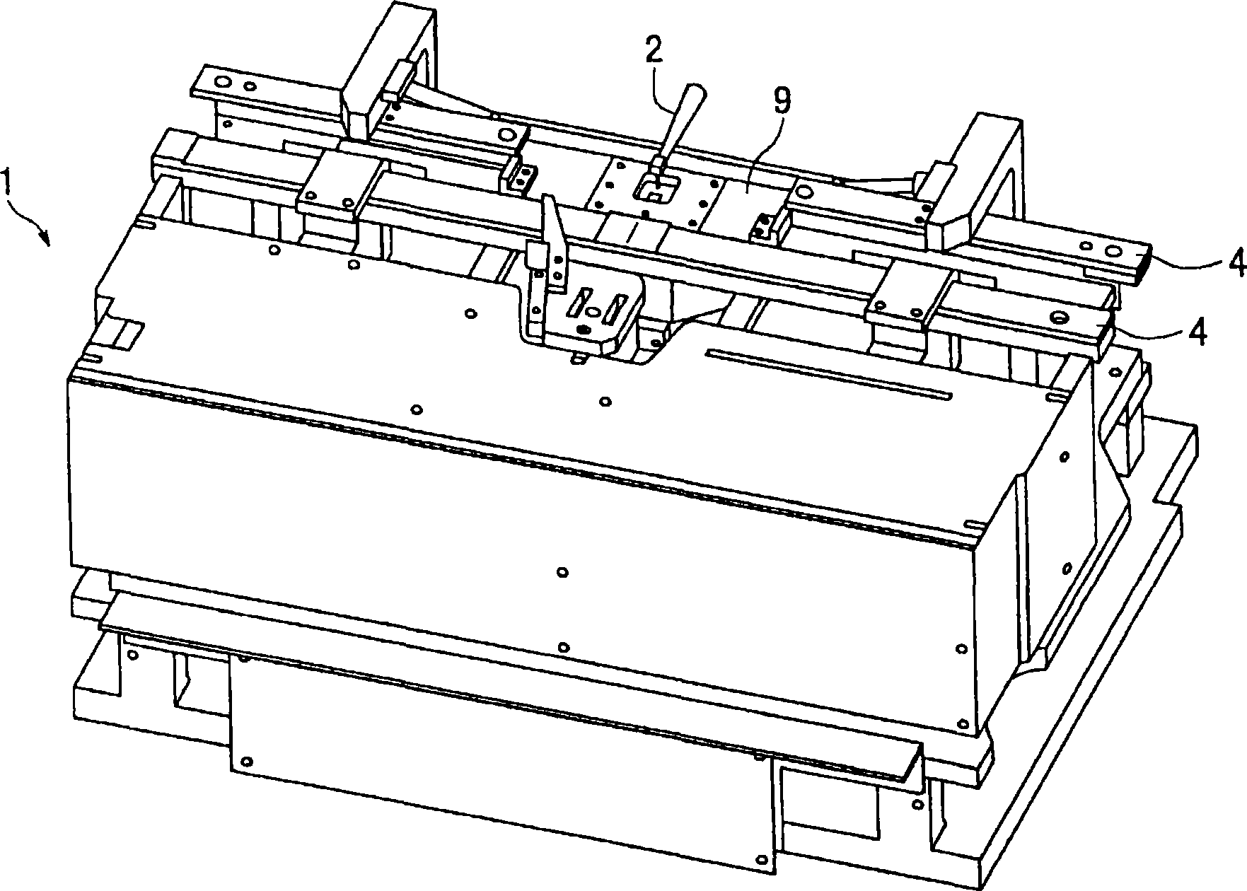
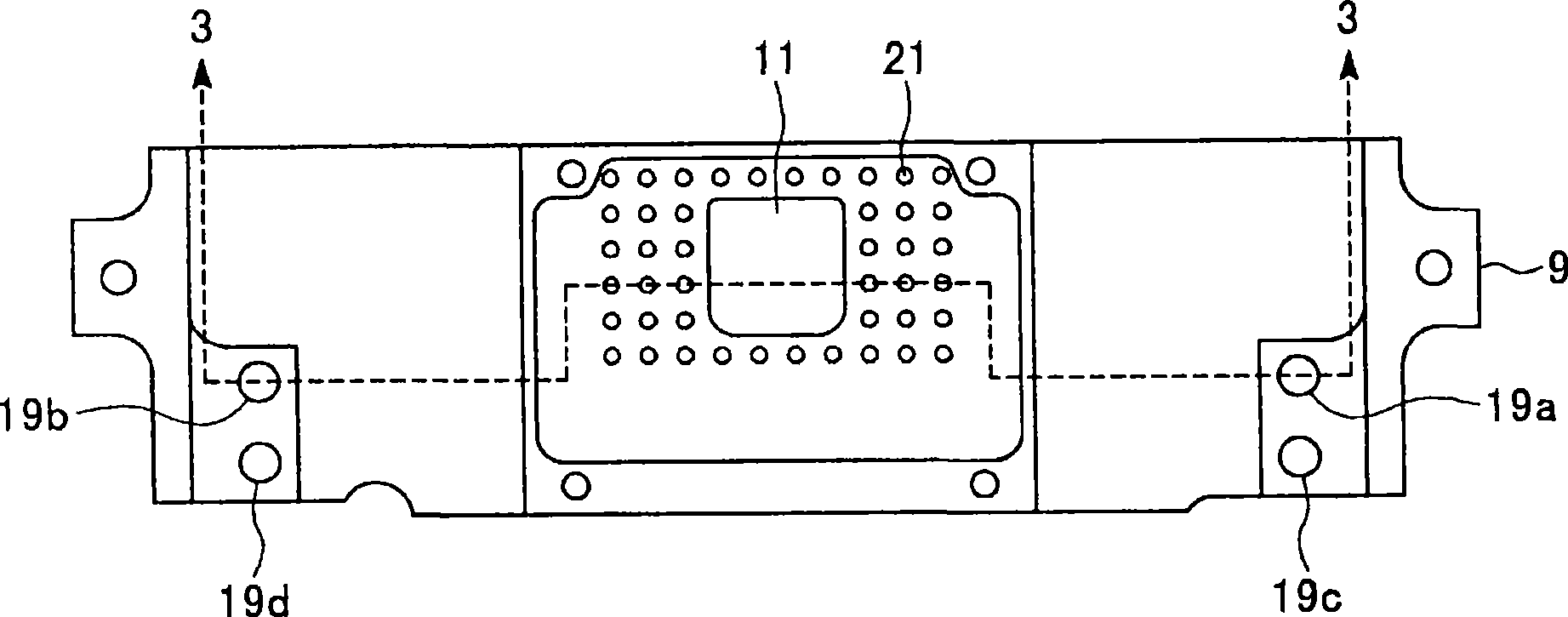
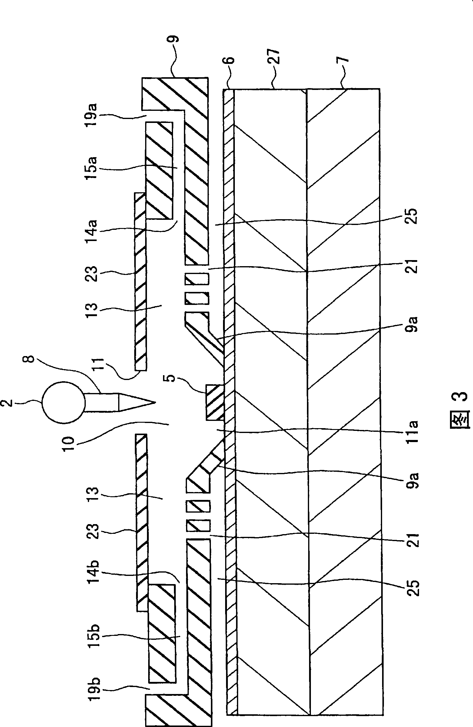
[0041] figure 1 It is a perspective view which shows the wire bonding apparatus which concerns on embodiment of this invention. figure 2 yes figure 1 A top view of the workholding shown. Figure 3 shows the use of figure 2 The shown workpiece holder is a cross-sectional view of the state where the workpiece is held on the stage and joined, that is, it shows the equivalent along the figure 2 Sectional section of the workholding fixture shown by arrow 3-3. Figure 4 (A) is intercepted with a surface along the gas path figure 2 Cutaway view of the workholding shown.

[0042] Such as figure 1 As shown, the wire bonding device 1 has: a bonding head 2 , a workpiece holder 9 , and a guide rail 4 . A joint stage is disposed below the work holder 9 . The lead frame 6 on which the bonding sheet 5 shown in FIG. 3 is mounted is a workpiece holder to be bonded. The w...


PUM


Abstract

A work clamp, and wire bonding apparatus, that even when the amount of antioxidant gas used is reduced, can satisfactorily inhibit the oxidation of bonding area. The work clamp is characterized by including interior hollow (10) providing an atmosphere of antioxidant gas; inferior aperture (11a) disposed under the interior hollow and provided to insert the bonding area in the interior hollow; superior aperture (11) disposed above the interior hollow and provided to expose the bonding area; cavity (13) covering the interior hollow and provided with an area larger than the opening area of the superior aperture; gas introduction ports (14a,14b) provided in the cavity and adapted to introduce the antioxidant gas in the cavity; and hole (21) connected to an inferior zone of the cavity and provided for blowing of the antioxidant gas introduced from the gas introduction ports to portions other than the bonding area of the work.

Description

technical field [0001] The present invention relates to a workpiece holder and a wire bonding apparatus using the same, and more particularly to a workpiece holder and a wire bonding apparatus capable of sufficiently suppressing oxidation of a bonding region even if the amount of oxidation-inhibiting gas used is reduced. Background technique [0002] Figure 5 It is a cross-sectional view showing a work holder of a conventional wire bonding apparatus. This work clamp has a mechanism for preventing oxidation of copper when the object to be joined is a bare copper wire lead frame or when the bonding lead is copper. This mechanism introduces an inert gas such as nitrogen gas into the opening 17 communicating with the bonding area. [0003] The semiconductor device holding the form of the lead frame 12 of the die 18 is arranged on a stage or an upper plate 29 of the wire bonding apparatus. The upper plate 29 has a heating mechanism for increasing the temperature of the lead fr...

Claims


Application Information

Patent Timeline
Patent Type & Authority Applications(China)
IPC IPC(8): H01L21/60
CPCH01L2924/01015H01L2924/01082H01L2224/85075H01L2924/01004H01L2924/01018H01L2924/15747H01L24/85H01L2924/01029H01L24/78Y10S228/904B23K37/0435H01L2224/45147B23K20/004H01L2224/85065H01L2224/78301H01L2924/01007H01L2224/78801H01L2224/48247H01L24/45H01L2924/01005H01L2924/01033H01L2924/01006H01L2924/01078H01L2224/78703B23K2201/40B23K2101/40H01L2924/00011H01L24/48H01L2224/781H01L2924/00014H01L2924/00012
Inventor 神藤力吉野秀纪久岛真美
Owner KAIJOO KK
Why Eureka
Try Eureka