Reflow furnace

A reflow furnace and heater technology, which is used in electric heating devices, electrical components, printed circuit manufacturing, etc., can solve the problems of overheating, thermal damage to solder paste of electronic components, and inability to heat printed circuit boards, and achieves excellent thermal stability. The effect of increasing the heat capacity

Active Publication Date: 2009-04-15
SENJU METAL IND CO LTD
View PDF8 Cites 7 Cited by
  • Summary
  • Abstract
  • Description
  • Claims
  • Application Information

AI Technical Summary

Problems solved by technology

If the temperature in the preheating zone or the main heating zone fluctuates up and down in this way, the printed circuit board cannot be heated ...

Method used


Image

  • Reflow furnace
  • Reflow furnace
  • Reflow furnace

Examples


Embodiment Construction

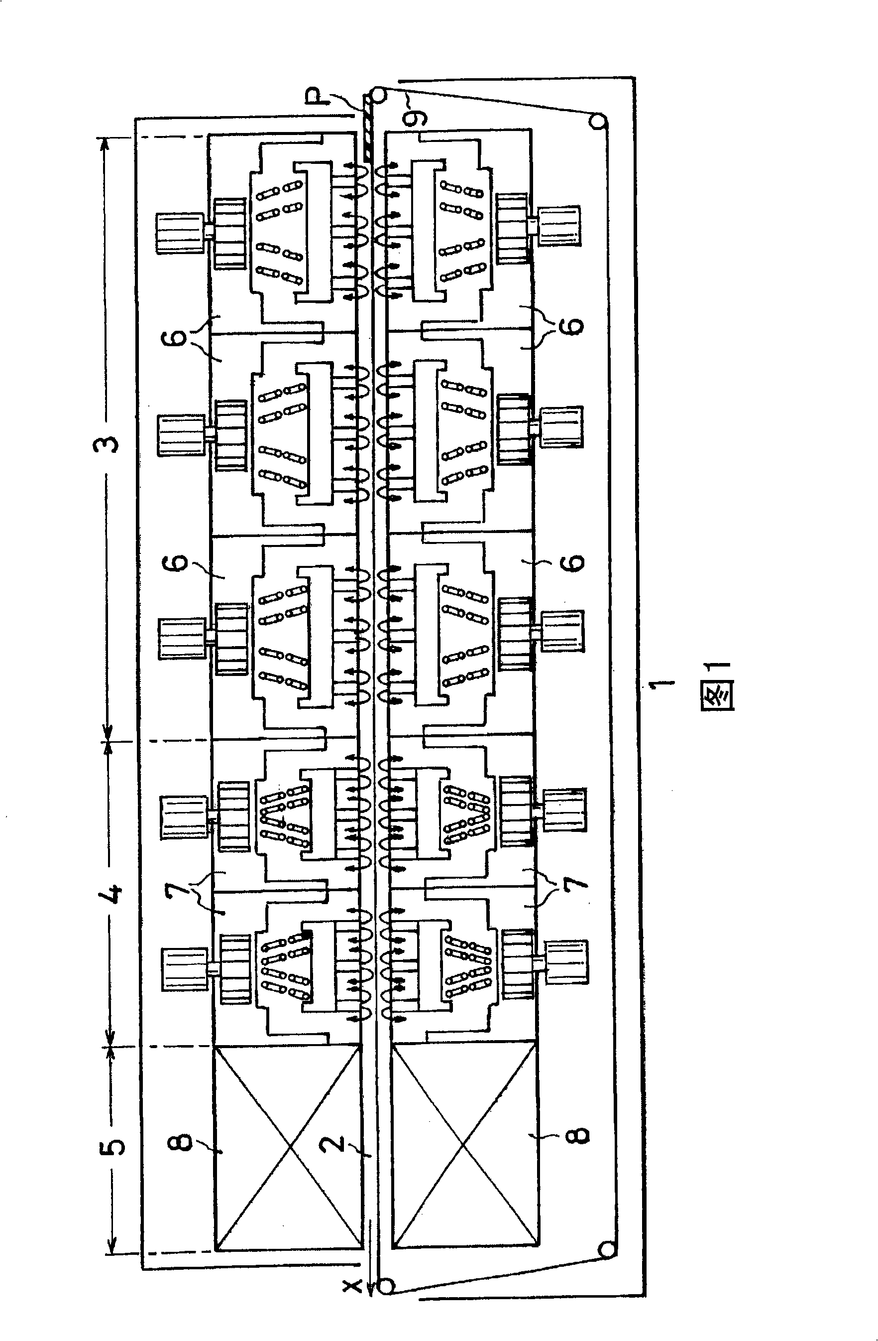
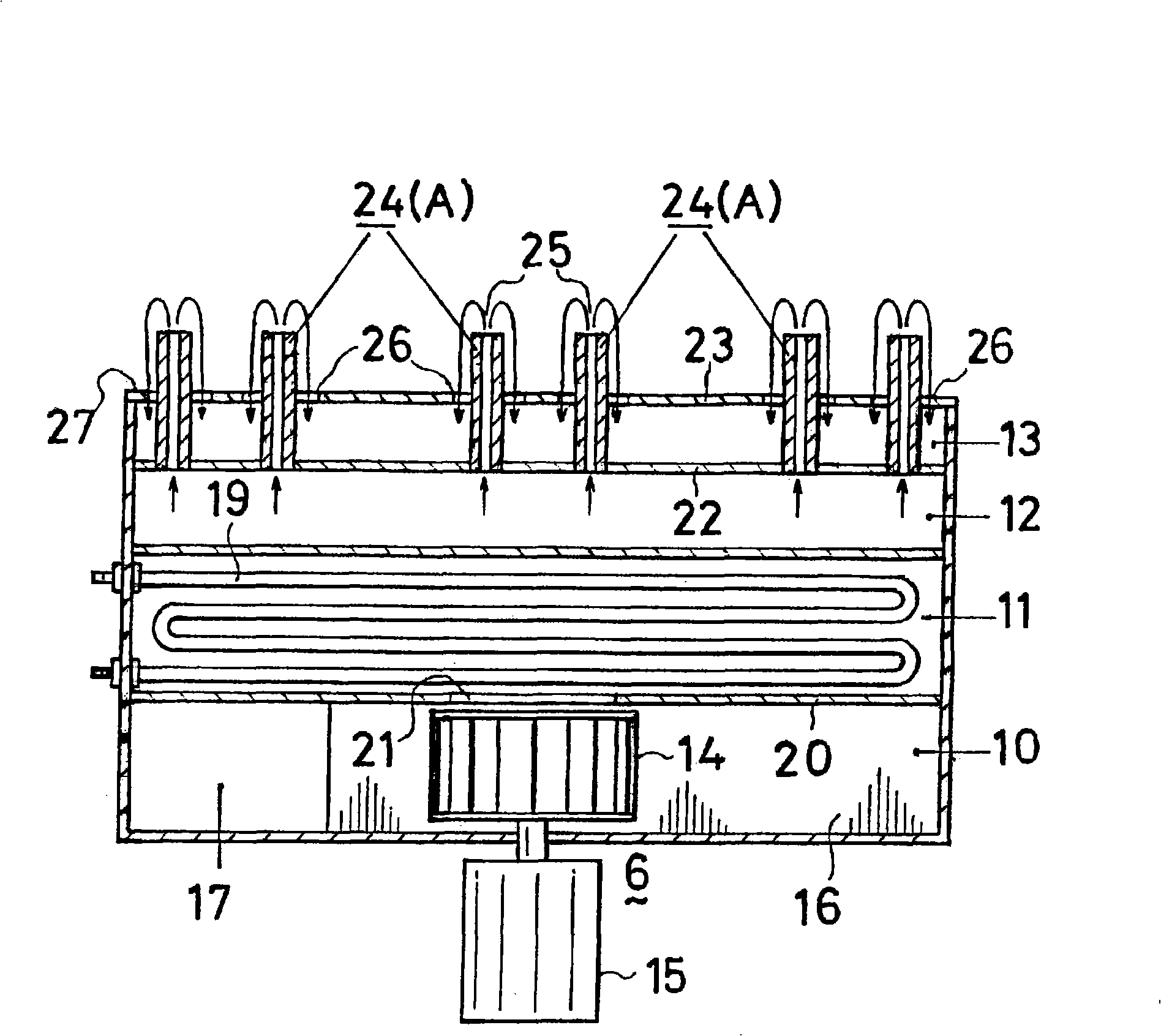
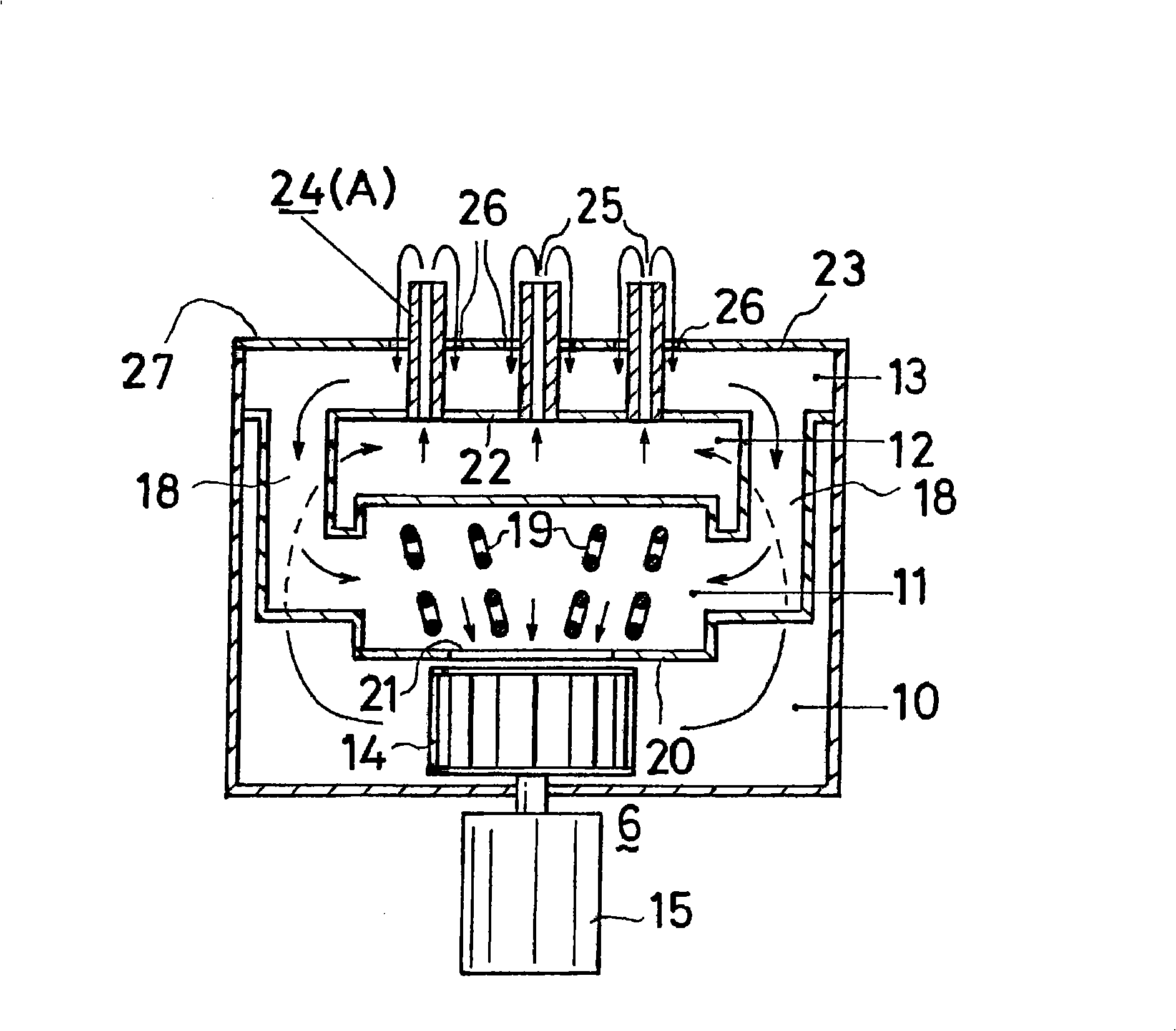
[0053] Hereinafter, the reflow furnace of this invention is demonstrated based on drawing. Fig. 1 is the front sectional view of reflow oven of the present invention, figure 2 It is a front sectional view of the hot air blowing heater installed in the reflow furnace of the present invention, image 3 is a side sectional view of hot air blowing out of the heater, Figure 4 It is a perspective view of various heater units forming a component nozzle, and Fig. 5 is a top view of a zigzag-shaped hot air blown out of the heater by the component nozzle, Figure 6 It is a partially enlarged perspective view of FIG. 5, and FIG. 7 is a top view of a hot air blowing heater with a wave-shaped nozzle of the component, Figure 8 It is a partially enlarged perspective view of FIG. 7, and FIG. 9 is a top view of a hot air blowing heater whose component nozzle is a louver-shaped section.

[0054] As shown in FIG. 1 , the reflow furnace 1 of the present invention has a tunnel-shaped muffle f...


PUM


Abstract

In conventional reflow furnaces having suction ports in the vicinity of many hot-air blowing ports, there have been some cases where the hot-air blowing nozzles are cooled when hot air at a reduced temperature after printed board heating is brought into contact with the hot-air blowing nozzle, since the hot-air blowing nozzle is thin. Furthermore, in conventional reflow furnaces having thick hot-air blowing nozzles, it has been difficult to change the shape of the nozzles to the shape suitable for a printed board, since the shape of the nozzle is fixed. In a reflow furnace, a hot-air blowing nozzle having a prescribed shape is formed by combining block heaters of various shapes. Furthermore, the block heater has vertical hot-air jetting ports in a thick board.

Description

technical field [0001] The present invention relates to a reflow furnace for melting solder paste coated on a printed circuit board for soldering. Background technique [0002] Soldering of printed circuit boards and electronic components using solder paste is generally performed in a reflow oven. The tunnel-shaped muffler of the reflow furnace is divided into a preheating zone, a main heating zone, and a cooling zone. Heaters are installed in the preheating zone and the main heating zone, and coolers are installed in the cooling zone. [0003] As heaters used in reflow furnaces, there are infrared heaters and hot air blowing heaters. Infrared heaters allow infrared rays to penetrate into printed circuit boards or electronic equipment to melt the solder paste applied to the soldering part, but because infrared rays travel in a straight line, they cannot sufficiently heat the soldering part covered by electronic components and become Gap welds. [0004] On the other hand, ...

Claims


Application Information

Patent Timeline
IPC IPC(8): H05K3/34B23K1/008B23K3/04B23K101/42
CPCB23K1/012B23K1/008H05K3/3494
Inventor 中村秀树
Owner SENJU METAL IND CO LTD
Why Eureka
Try Eureka