
Trap type capacitor fixing device

A technology for fixing devices and capacitors, which is used in capacitors, electrolytic capacitors, capacitor parts and other directions to achieve the effect of reducing volume, enhancing shock resistance, and optimizing electrical performance.

Inactive Publication Date: 2011-07-13
CHINA CNR CORPORATION
View PDF0 Cites 2 Cited by
  • Summary
  • Abstract
  • Description
  • Claims
  • Application Information

AI Technical Summary

Problems solved by technology

[0005] In view of the above-mentioned problems in the prior art, the purpose of the present invention is to study and design a novel trap-type capacitor fixing device, thereby solving the problem of inconvenient installation of electrolytic capacitors Dismantling, taking up a large space, easy to wear out capacitors, prone to leakage, short circuit hazards, etc.

Method used


Image

  • Trap type capacitor fixing device
  • Trap type capacitor fixing device
  • Trap type capacitor fixing device

Examples


Embodiment Construction

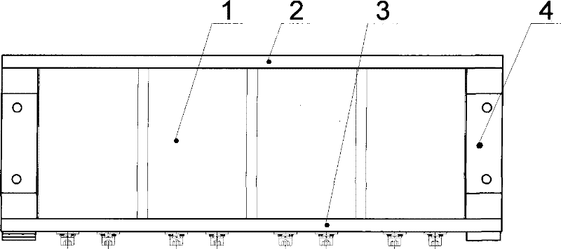
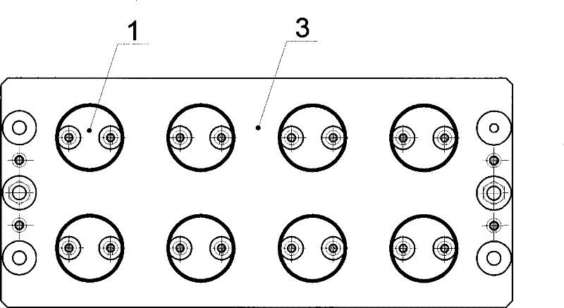
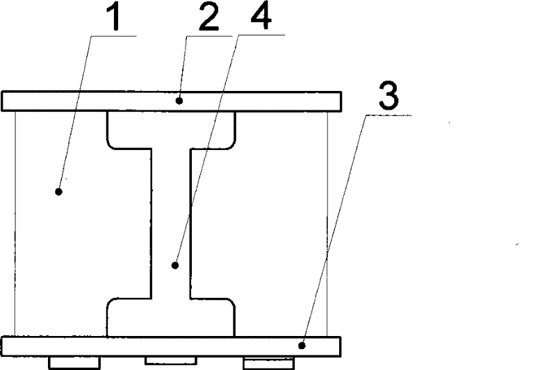
[0020] Specific examples of the present invention are attached figure 1 As shown, the trap-type capacitor fixing device of the present invention is composed of an electrolytic capacitor 1 , a capacitor fixing upper plate 2 , a capacitor fixing lower plate 3 , and a fixing bracket 4 . The left and right ends of the capacitor fixed upper plate 2 and the capacitor fixed lower plate 3 are equipped with fixed brackets 4, the fixed brackets 4 are in the shape of "I" and fixed by screws; the inner surface of the capacitor fixed upper plate 2 is processed with 8 grooves , distributed in two rows with equal distance, as attached figure 2 shown. The capacitor fixed lower plate 3 is processed into two layers of stepped holes at the corresponding positions of the capacitor fixed upper plate 2 grooves, as attached image 3 shown. The terminal of the electrolytic capacitor 1 is facing the stepped hole of the capacitor fixing lower plate 3 , and the other end extends into the groove of ...


PUM


Abstract

The invention provides a trap-typed capacitor fixing device, consisting of an electrolytic capacitor, an upper capacitor fixing plate, a lower capacitor fixing plate and a fixing support frame. The fixing support frame is arranged at the left and right ends of the upper capacitor fixing plate and the lower capacitor fixing plate. The fixing support frame takes the shape of 'I' and is fixed by bolts. Six to twelve grooves are processed on the internal surface of the upper capacitor fixing plate and are distributed in two rows at intervals. Two layers of counterbores are processed on the lower capacitor fixing plate at the positions corresponding to the grooves of the upper capacitor fixing plate. The terminal of the electrolytic capacitor faces the counterbores of the lower capacitor fixing plate while the other end stretches into the grooves of the upper capacitor fixing plate. The device fastens the capacitor module and facilitates modularized mounting and demounting. The device has excellent insulativity. The device adopts an integral design, wherein, fixing, mounting and wiring of the capacitor are integrated. The device is applicable for the fields of rail vehicle, light rail,subway, Maglev train, industrial converter, etc.

Description

technical field [0001] The invention relates to a fixing device for capacitors. Background technique [0002] At present, the converter power supply products developed by using power electronic technology have been widely used in various fields such as electric power, military industry, industry, commerce, agriculture, etc., and only one inverter is used in all walks of life all over the world. With the continuous improvement and development of power electronics application technology, the advantages of converters in energy saving, environmental protection and other aspects are increasingly reflected, and have been widely recognized by users. [0003] Due to its vast market space and social needs, converters are also rapidly developing towards small size and large capacity. The core part of the cabinet structure is the power unit, and the fixing, installation and wiring of DC voltage support capacitors are One of the most important issues of the electrical structure of the...

Claims


Application Information

Patent Timeline
Patent Type & Authority Patents(China)
IPC IPC(8): H01G9/004H01G9/26
Inventor 张可飞马惠春付强
Owner CHINA CNR CORPORATION
Learn More