
Thermal storage defrosting or temperature controlling mixed working substance copious cooling throttle refrigeration system

A refrigeration system and mixed working medium technology, applied in refrigerators, refrigeration components, refrigeration and liquefaction, etc.

Inactive Publication Date: 2009-04-01
TECHNICAL INST OF PHYSICS & CHEMISTRY - CHINESE ACAD OF SCI
View PDF3 Cites 20 Cited by
  • Summary
  • Abstract
  • Description
  • Claims
  • Application Information

AI Technical Summary

Problems solved by technology

However, when this scheme is used in defrosting conditions, additional measures such as electric heating are required

Method used


Image

  • Thermal storage defrosting or temperature controlling mixed working substance copious cooling throttle refrigeration system
  • Thermal storage defrosting or temperature controlling mixed working substance copious cooling throttle refrigeration system

Examples


Embodiment 1

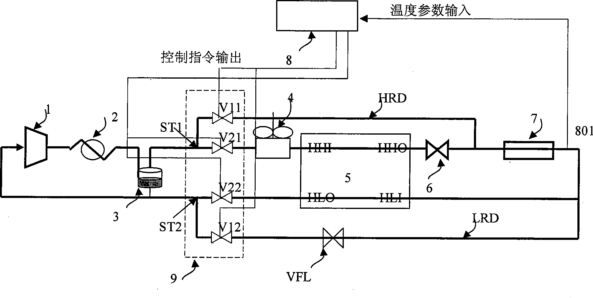
[0048] Embodiment 1: adopt figure 1 The refrigeration process and control system shown include compressor 1, heat accumulator 2, lubricating oil separator 3, aftercooler 4, recuperation heat exchanger unit 5, throttling refrigeration element 6, evaporator unit 7, and control unit 8 and a control execution unit group 9; the control execution unit group 9 includes a high-pressure three-way pipeline ST1, a high-pressure heating control valve V11, a high-pressure heating pipeline HRD, a high-pressure refrigeration control valve V21, a low-pressure three-way pipeline ST2, and a low-pressure heating control valve V12, low-pressure heating pipeline and low-pressure refrigeration control valve V22; see system connection figure 1 As shown, the refrigeration circuit C1 is composed of a compressor 1, a heat accumulator 2, a lubricating oil separator 3, an aftercooler 4, a recuperation heat exchanger unit 5, a throttling refrigeration element 6 and an evaporator unit 7; Compressor 1, hea...

Embodiment 2

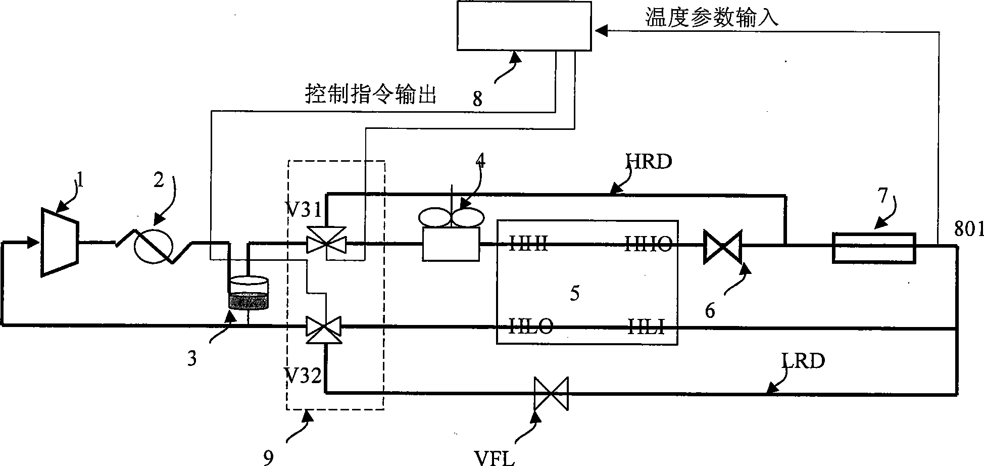
[0052] Embodiment 2: adopt figure 2 The refrigeration process and control system shown include compressor 1, heat accumulator 2, lubricating oil separator 3, aftercooler 4, recuperation heat exchanger unit 5, throttling refrigeration element 6, evaporator unit 7, and control unit 8 and the control execution unit group 9; the control execution unit group 9 includes a high-pressure three-way reversing valve V31, a high-pressure heating pipeline HRD, a low-pressure three-way reversing valve V32, a low-pressure heating pipeline LRD and a flow control element VFL; system connection way see figure 2 As shown, the refrigeration circuit C1 is composed of a compressor 1, a heat accumulator 2, a lubricating oil separator 3, an aftercooler 4, a recuperation heat exchanger unit 5, a throttling refrigeration element 6 and an evaporator unit 7; Compressor 1, heat accumulator 2, lubricating oil separator 3, high-pressure heating pipeline HRD, evaporator unit 7, and low-pressure heating pi...


PUM


Abstract

The invention relates to a mixed-work substance deep-cooling throttle refrigeration system which utilizes restored compression heat for realizing evaporator defrosting and temperature change controlling, comprising a compressor, a heat accumulator, a lubricant separator, an aftercooler, an regenerated heat exchanger unit, throttle refrigeration elements, an evaporator unit, a control unit and a control execution unit set. The control execution unit set comprises a controllable heating valve set and a controllable refrigerating valve set and can realize controllable operation of heating and refrigerating; as to the different working conditions of the mixed-work substance deep-cooling throttle refrigeration system, the controlling method can realize the refrigerating and heating of the evaporator so as to meet controlling demands in different working conditions according to the comparison between a pre-set value and an input parameter and by controlling the opening and closing of the controllable valves and the change of the flowing direction. The system can utilize the restored compressed heat to realize evaporator defrosting and temperature change controlling without extra heating sources, thus reducing the energy consumption of the system.

Description

technical field [0001] The invention relates to a refrigeration system and a control method thereof in the field of low-temperature refrigeration technology, and in particular to a cryogenic throttling refrigeration of a mixed working medium that utilizes stored compression heat to realize defrosting of an evaporator or variable temperature control heat storage defrosting or temperature control system. Background technique [0002] The cryogenic multi-component mixed working medium throttling refrigerator with heat recovery measures has the advantages of high efficiency, reliability and low manufacturing cost. It is widely used in the fields of energy, chemical industry and low temperature engineering, and is used to realize device cooling and liquefaction of industrial gases. Among them, the application in the field of semiconductor production and vacuum is one of the important manifestations of mixed working fluid throttling refrigeration technology. The use of multiple m...

Claims


Application Information

Patent Timeline
IPC IPC(8): F25B47/02F25B49/02
Inventor 公茂琼吴剑峰
Owner TECHNICAL INST OF PHYSICS & CHEMISTRY - CHINESE ACAD OF SCI
Learn More