Core of cylindrical battery and method for assembling the core into the battery case

A technology for cylindrical batteries and battery casings, which is applied in the field of battery cells loaded into battery casings and cylindrical batteries. It can solve the problems affecting battery durability and unfavorable reliable connection, etc., and achieve reliable connection and reasonable structure. Effect

Inactive Publication Date: 2009-03-25
SHENZHEN BAK BATTERY CO LTD
View PDF0 Cites 8 Cited by
  • Summary
  • Abstract
  • Description
  • Claims
  • Application Information

AI Technical Summary

Problems solved by technology

[0003] In such a battery structure, there is no design arrangement to form a fixed connection between the winding core and the casing. The winding core is directly placed in the cavity in the casing. The filling space of the electrolyte and the accommodation space for the reasonable gas production during the working process of the battery are reserved between the core and the winding core, which is unfavorable for the reliable connection between the positive and negative electrodes of the battery and the positive and negative terminals of the battery. Especially when the battery is used in frequent moving situations, or when the battery size is large and the winding core is heavy, it may affect the durability of the battery

Method used


Image

  • Core of cylindrical battery and method for assembling the core into the battery case
  • Core of cylindrical battery and method for assembling the core into the battery case
  • Core of cylindrical battery and method for assembling the core into the battery case

Examples


Embodiment 1

[0035] Embodiment one (cell of cylindrical battery)

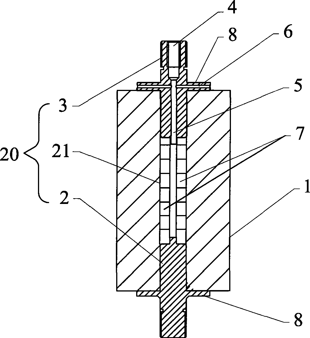
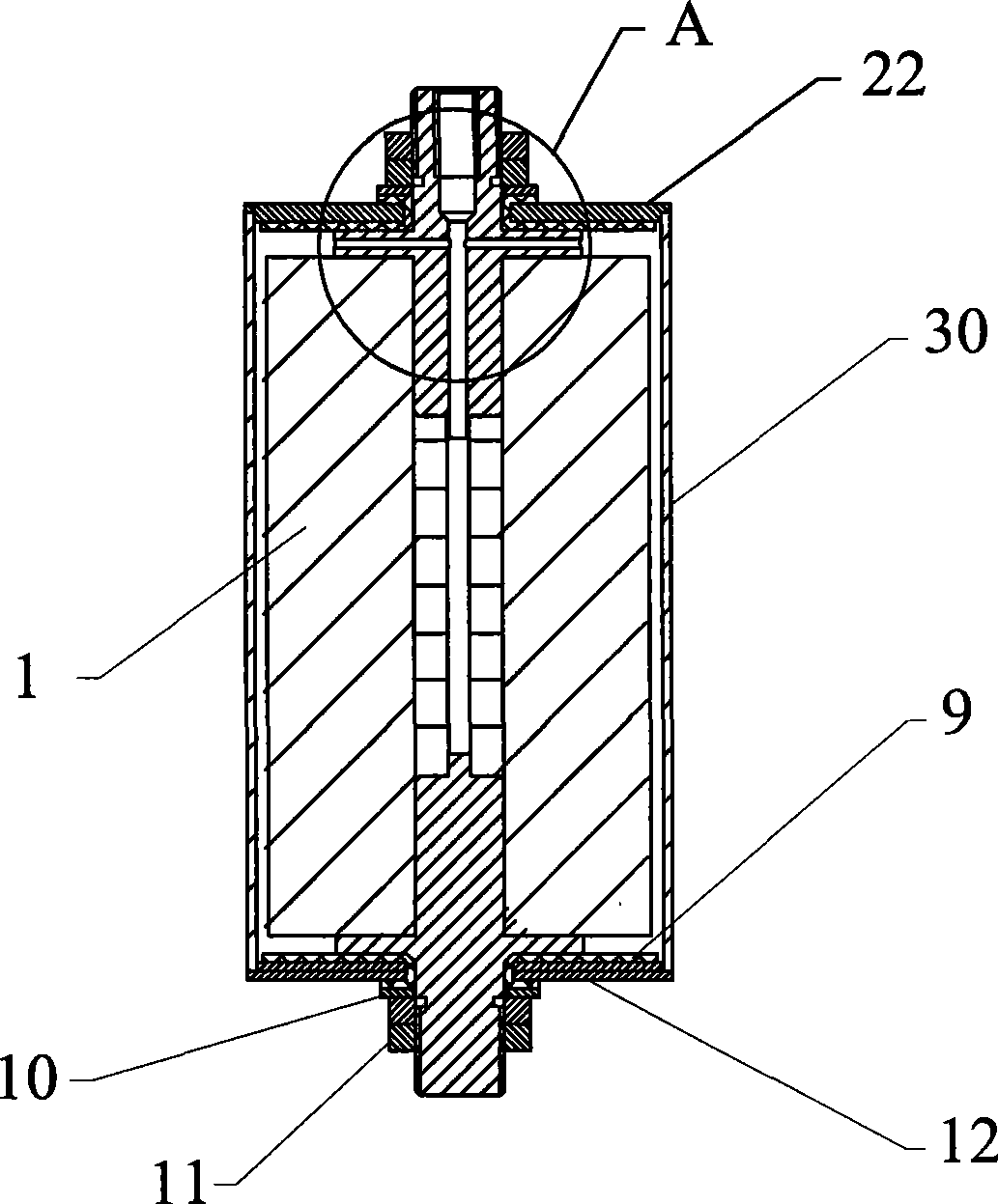
[0036] figure 1 , figure 2 and image 3 One embodiment of the cell of the cylindrical battery of the present invention is shown. figure 2 shows the use of figure 1 The structure of the battery with the cells shown.

[0037] The cylindrical cell includes a reel 20 and a reel 1 wound by positive and negative pole pieces and a separator. The reel 1 is wound on the reel 20, and the reel 20 runs through the reel 1; the lower section of the reel 20 is the positive end 2 1. The upper section is the negative terminal 3, the positive terminal 2 is electrically connected to the positive electrode sheet of the winding core 1, the negative terminal 3 is electrically connected to the negative electrode sheet of the winding core 1, and the middle section of the reel 20 is an insulating member 21, which is connected to the positive electrode sheet. The pole 2 and the negative pole 3 are fixedly connected together; the end of the po...

Embodiment 2

[0038] Embodiment 2 (the method for packing the electric core in embodiment 1 into a cylindrical casing)

[0039] The process of packing the cylindrical cell in embodiment 1 into the cylindrical shell of the battery can be found in figure 2 -- Figure 7 .

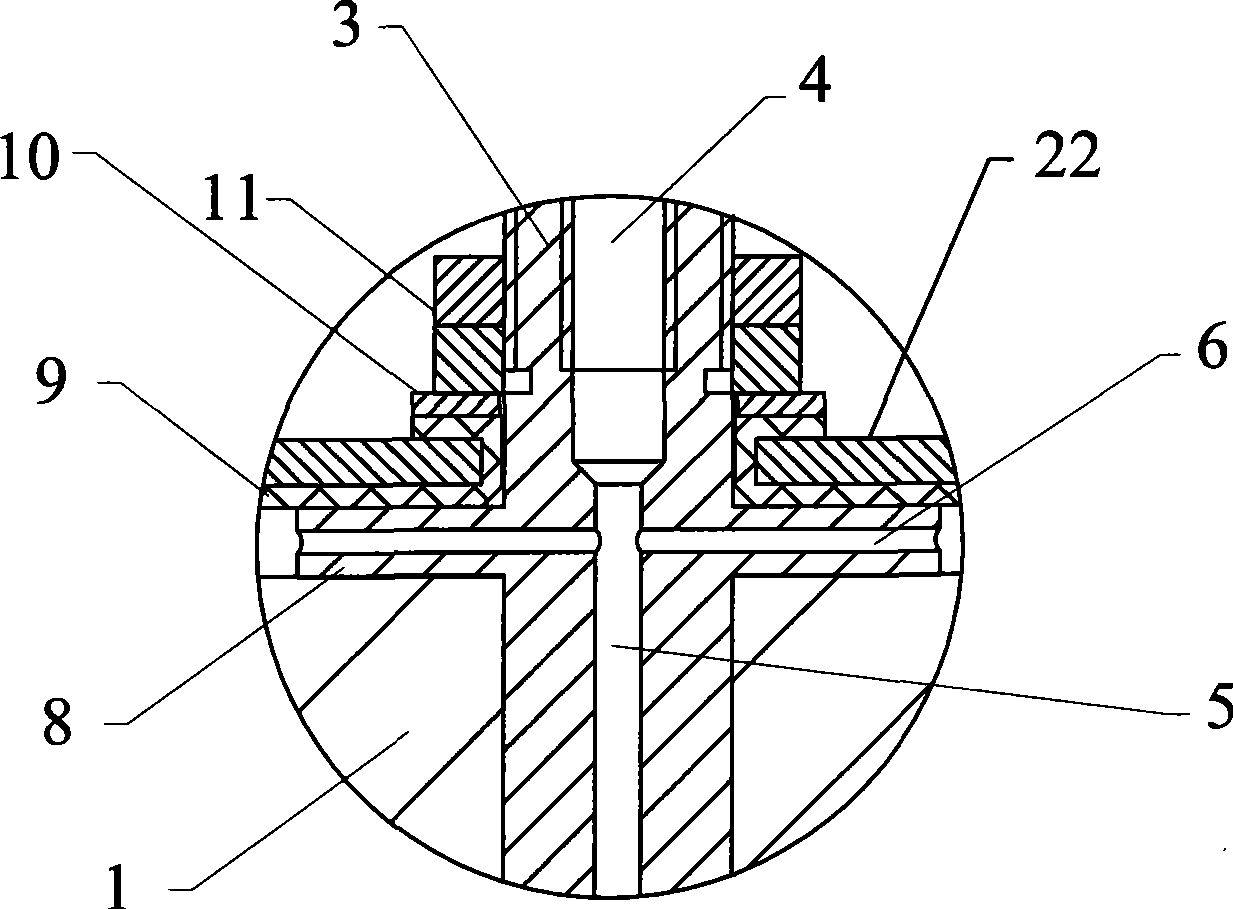
[0040] Such as Figure 4As shown, before the cell is loaded into the cylindrical case of the battery, a second end cap 12 with a middle hole is installed on the positive end 2, and the second end cap 12 is located between the positive end 2 and the second end cap 12. The insulating sealing ring 9 is put on the positive end 2, and then the gasket 10 and the nut 11 are installed on the positive end 2 in sequence, and the nut 11 is tightened so that the second end cap 12 is pressed by the pressure plate 8 and the nut on the positive end 2. Cap 11 is clamped.

[0041] Such as Figure 5 As shown, the upper port of the battery cylindrical casing 30 is welded with a first end cap 22 with a middle hole, and the insulating sea...


PUM


Abstract

The invention provides an electric core of a cylindrical battery. The electric core comprises a roll core and a core axis penetrating the roll core. Positive and negative pole pieces and a diaphragm are wound on the core axis, and the two ends of the core axis are exposed out of the two end surfaces of the roll core. The invention further provides a method for mounting the electric core into the housing of the battery. By adopting the electric core of the cylindrical battery and the method for mounting the electric core into the housing of the battery, the core axis is fixed on the end cover or at the bottom part of the housing when being assembled; the relative fixing among the end cover, the housing, the core axis and the roll core provides the possibility of forming reliable connection between the positive pole piece and the negative pole piece and the positive electrode and the negative electrode of the battery; the center of gravity of the whole roll core is on the core axis; the core axis is sleeved on the end cover or in the center of the bottom part of the housing of the battery, the center of gravity of the battery is positioned in the geometric center of the outline thereof, and the structure is reasonable. The electric core of the cylindrical battery and the method for mounting the electric core into the housing of the battery are especially suitable for batteries with larger sizes or with heavier roll cores such as power batteries.

Description

technical field [0001] The invention relates to battery processing technology, in particular to a battery cell of a cylindrical battery which facilitates the reliable connection of positive and negative pole pieces to the positive and negative electrodes of the battery and a method for loading the battery cell into a battery case. Background technique [0002] The structure of the battery includes a case, a winding core and an end cap. The winding core is formed by winding a positive electrode sheet, a negative electrode sheet, and a separator located between the positive and negative electrode sheets. The battery assembly method in the prior art is usually to insert the winding core into the casing, weld the positive electrode sheet and the negative electrode sheet to the positive electrode terminal and the negative electrode terminal of the battery respectively, and then use welding or other methods to make the end cap on the open end of the casing and The housing forms a...

Claims


Application Information

Patent Timeline
IPC IPC(8): H01M10/04H01M6/00
CPCY02E60/10Y02P70/50
Inventor 刘付勇袁红庆
Owner SHENZHEN BAK BATTERY CO LTD
Why Eureka
Try Eureka