Silicon smelting electric furnace waste heat power generation process flow and configuration
What is Al technical title?
Al technical title is built by PatSnap Al team. It summarizes the technical point description of the patent document.
A technology for waste heat power generation and process flow. It is applied in lighting and heating equipment, mechanical equipment, and process efficiency improvement. It can solve the problems of immature flue gas extraction technology, high failure rate of heat exchangers, and fluctuation of waste heat. The effect of small leakage of cold air, improving the utilization rate of waste heat and prolonging life
Active Publication Date: 2009-03-25
CITIC HEAVY INDUSTRIES CO LTD +1
View PDF0 Cites 14 Cited by
Summary
Abstract
Description
Claims
Application Information
AI Technical Summary
This helps you quickly interpret patents by identifying the three key elements:
Problems solved by technology
Method used
Benefits of technology
Problems solved by technology
[0006] Due to the immature flue gas extraction technology, waste heat fluctuations, dust accumulation in heat exchangers, and insufficient heat consumption by heat users, the failure rate of heat exchangers is high and the input rate is low, and most of the waste heat is still wasted.
Method used
Image
Click on the blue label to locate the original text in one second.
Reading with bidirectional positioning of images and text.
Examples
Embodiment Construction
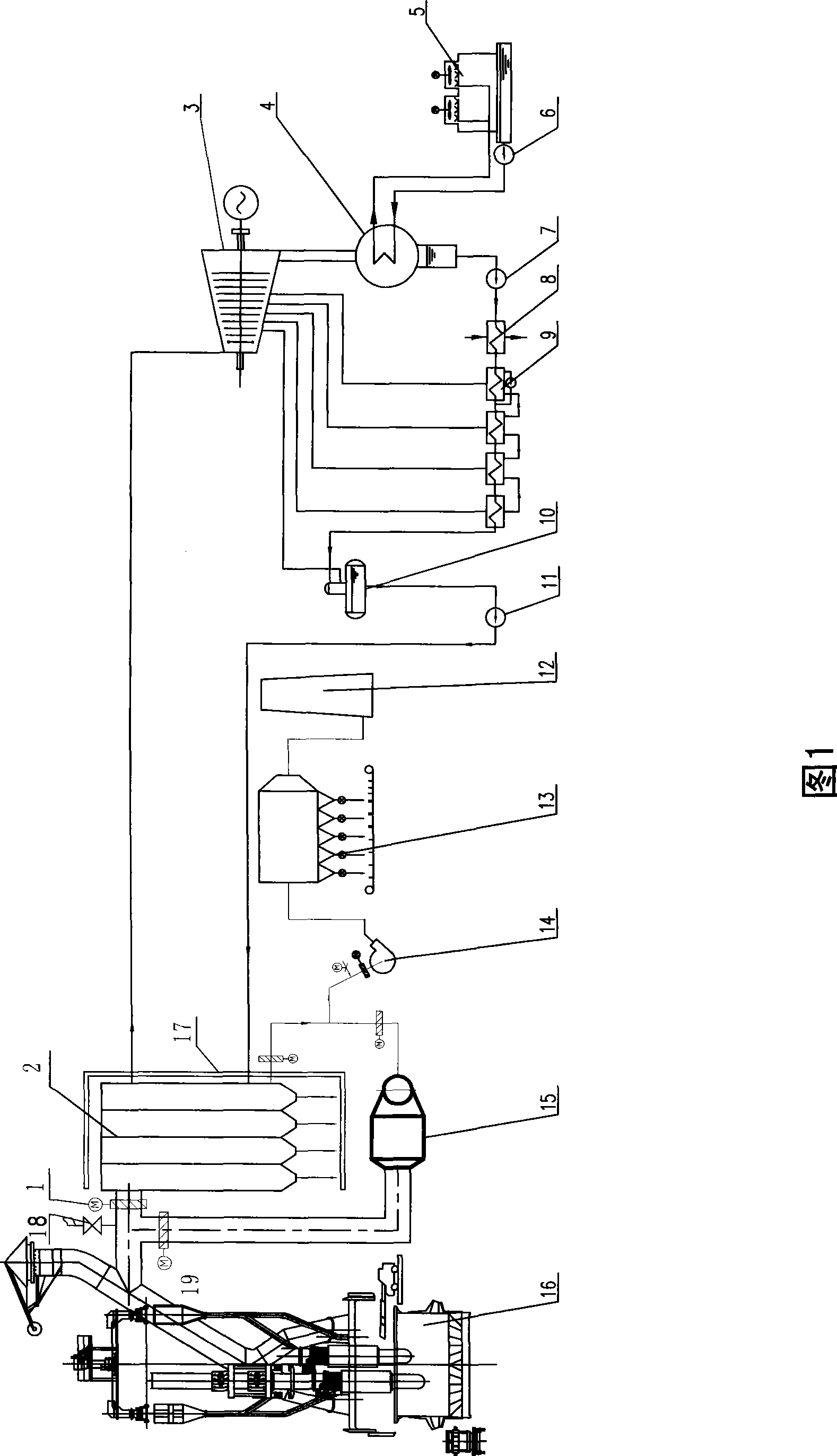
[0031] The waste heat power generation process of the silicon smelting electric furnace of the present invention is that the waste gas discharged from the top of the silicon smelting electric furnace is collected through a semi-closed smoke hood and introduced into the waste heat boiler through the pipeline. The superheated steam generated by the waste heat boiler enters the turbogenerator unit through the main steam valve to generate electricity, and the exhaust steam at the tail is cooled in the condenser by a circulating water system composed of a cooling tower and a circulating water pump. It is condensed water, and the condensed water enters the thermal deaerator after being heated by the condensate pump, steam seal heater and several low-pressure heaters. The steam extraction in the boiler heats the condensed water and desalinated water to about 104°C. After removing the oxygen in the water, it is pressurized by the feed water pump and enters the waste heat boiler. The fe...
PUM
Abstract
The invention provides silicon smelting electric furnace waste heat power generating equipment, which consists of a valve 1, a waste heat boiler 2, a turbo generator 3, a vapor condenser 4, a cooling tower 5, a circulating water pump 6, a condensing water pump 7, a vapor seal heater 8, a low-pressure heater 9, a deaerator 10, a feed water pump 11, a chimney 12, a bag dust collector 13, an induced draft fan 14, a air cooler 15, a steel ball collection conveying distribution lifting device 17, a mixing cold air valve 18 and a by-pass valve 19, wherein waste flue gas discharged by a silicon smelting electric furnace 16 is introduced into the waste heat boiler to release partial heat; and when the temperature of the waste flue gas is reduced to nearly 180 DEG C, the waste flue gas enters the bag dust collector through the induced draft fan, and finally is discharged to atmosphere through the chimney. The desalted water enters the waste heat boiler through the feed water pump, vapor generated by the waste heat boiler enters the turbo generator; and after the vapor does work, the vapor enters the vapor condenser to be condensed into water, and the water enters the deaerator through a condensate removal pump, and the deoxidized water enters the waste heat boiler through the feed water pump. The silicon smelting electric furnace waste heat power generating equipment has the advantages of good energy saving effect, little investment and low cost.
Description
technical field [0001] The invention belongs to the technical field of waste heat power generation, and is especially suitable for a process flow and equipment configuration of waste heat power generation of a silicon smelting electric furnace. Background technique [0002] As we all know, a large amount of waste heat flue gas is discharged in the smelting process of silicon smelting, ferrosilicon smelting, etc., and they carry a large amount of waste heat. If they are not utilized, a large amount of waste heat resources will be wasted in vain. [0003] At present, there are two main ways to deal with the waste heat of flue gas as mentioned above: [0004] The first is direct cooling and emission. A large amount of flue gas generated by the electric furnace in the production process is cooled by the air cooler, and the waste heat is discharged into the atmosphere. The temperature of the flue gas drops below 180°C, and the dust is collected by the bag filter before being disc...
Claims
Application Information
Patent Timeline
Application Date:The date an application was filed.
Publication Date:The date a patent or application was officially published.
First Publication Date:The earliest publication date of a patent with the same application number.
Issue Date:Publication date of the patent grant document.
PCT Entry Date:The Entry date of PCT National Phase.
Estimated Expiry Date:The statutory expiry date of a patent right according to the Patent Law, and it is the longest term of protection that the patent right can achieve without the termination of the patent right due to other reasons(Term extension factor has been taken into account ).
Invalid Date:Actual expiry date is based on effective date or publication date of legal transaction data of invalid patent.