
Electrical connector for circuit board

A technology of electrical connectors and circuit substrates, which is applied in the direction of circuits, connections, electrical components, etc., can solve the problems of relative position deviation, unstable contact, unevenness, etc., and achieve the effect of stable contact, large allowable range, and guaranteed allowable range

Active Publication Date: 2009-03-18
HIROSE ELECTRIC GROUP
View PDF1 Cites 2 Cited by
  • Summary
  • Abstract
  • Description
  • Claims
  • Application Information

AI Technical Summary

Problems solved by technology

In other words, the interference between the two contact parts facing each other with respect to the transfer substrate in the storage tank is not equal.
Therefore, when the transmission substrate is inserted into the storage tank, the contact pressure between the contact portion and the connection piece of the transmission substrate is uneven on both surfaces of the transmission substrate, and the contact on the side with the lower contact pressure becomes unstable.
[0008] In addition, even if there is no manufacturing error, etc., and the connector is assembled under the condition that the terminal is not inclined in the receiving groove, sometimes the relative position of the terminal and the corresponding receiving groove will be changed due to the external force of the connector during use. deviation, the result is the same as above, the contact between the contact part and the transmission substrate becomes unstable

Method used


Image

  • Electrical connector for circuit board
  • Electrical connector for circuit board
  • Electrical connector for circuit board

Examples


Embodiment Construction

[0044] Embodiments of the present invention will be described below with reference to the drawings.

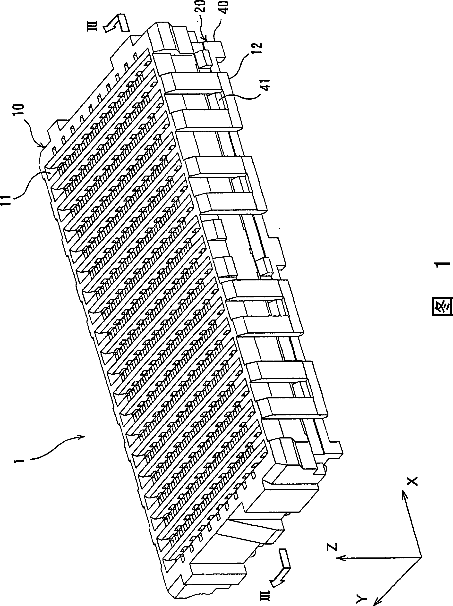
[0045] FIG. 1 is a perspective view showing the whole of the electrical connector according to the present embodiment. As shown in this figure, the electrical connector 1 (hereinafter referred to as "connector 1") has a substantially rectangular parallelepiped shape and is assembled by a relay component receiving body 10 and a relay component connecting body 20. The relay component receiving body 10 Receiving a relay component (not shown), the relay component connecting body 20 arranges and maintains a plurality of terminals electrically connected to the inserted relay component.

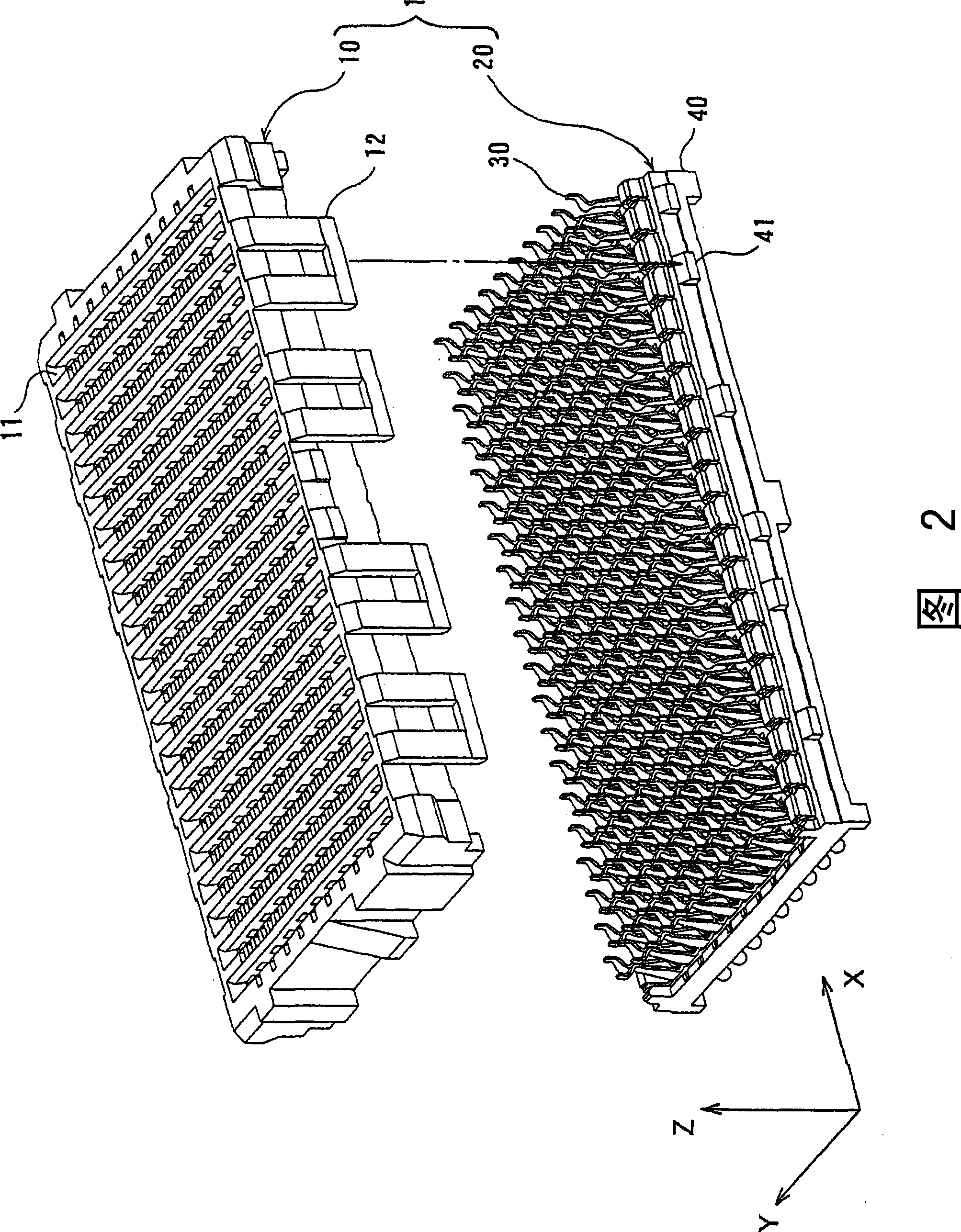
[0046] FIG. 2 is an exploded perspective view of the electrical connector 1 of FIG. 1 . In the present embodiment, as shown in the figure, three directions orthogonal to each other in a three-dimensional space, that is, the longitudinal direction, the width direction and the height direction of the...


PUM


Abstract

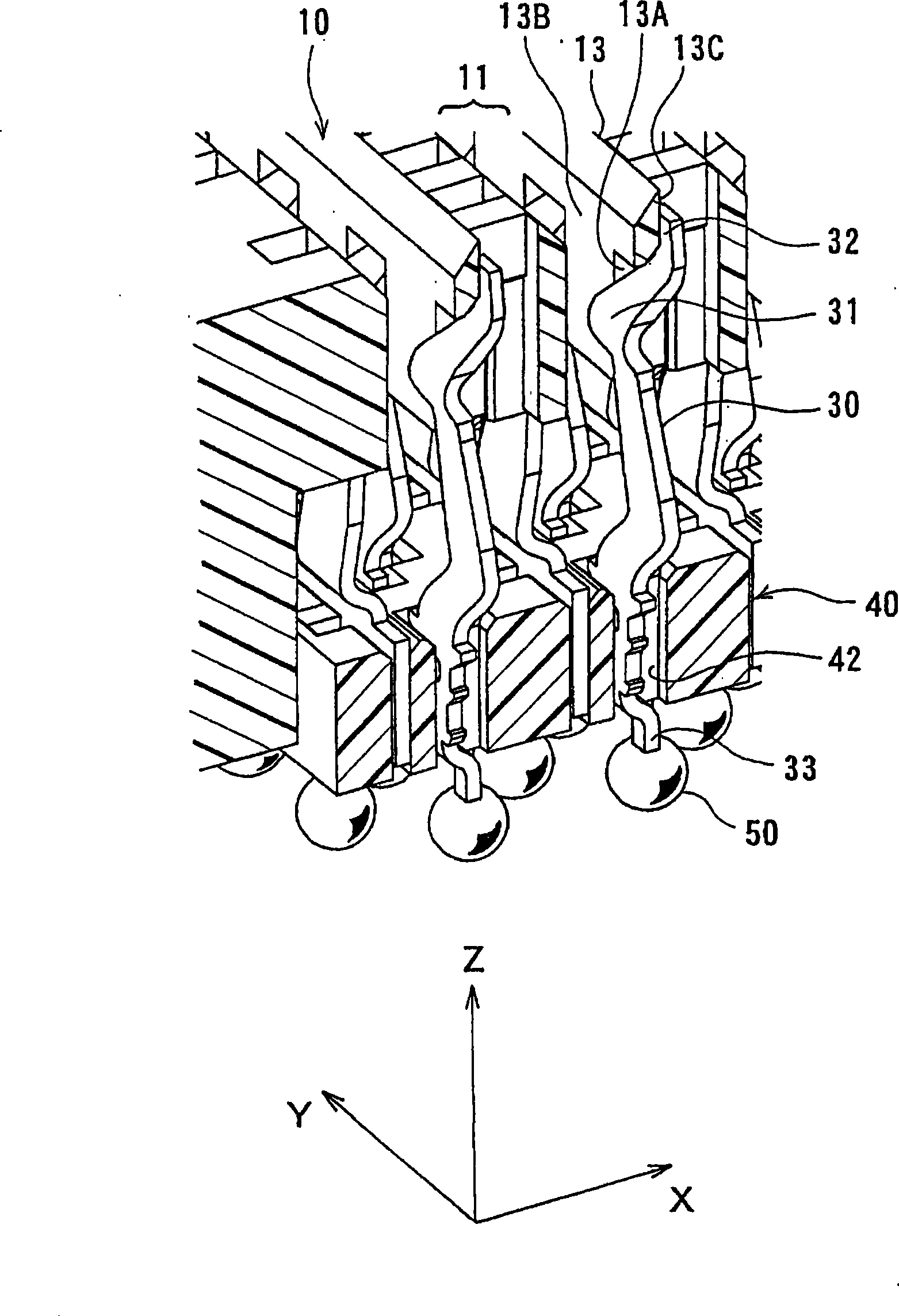
The invention provides an electrical connector which ensures stability in contact with a relay part even if deviation is generated between parts. In the connector (1), a relay member receiving body (10) is assembled on a spreading surface of a plurality of rows of terminal groups of terminals (30, 30') relatively successfully kept on a terminal holder (40), namely on an assembly direction orthogonally of a terminal arrangement surface with the terminal holder (40), wherein a plurality of receiving grooves (11) of the relay member receiving body (10) and the receiving relay member (P) are respectively formed spreading along the assembly direction, a plurality of terminals (30, 30') are upright relative to the terminals, kept on one end side of the terminals (30, 30'). Contact parts (31, 31') contacted with the relay part (P) and deformed flexurally are arranged on the other end side of the terminals (30, 30') toward the inner side of the receiving grooves (11). A front end part of the other end side of the plurality of terminals (30, 30') are bunted with the relay member receiving body (10), subjected to precompression of the direction deviating from the relay part (P) on the flexural direction of the contact parts (31, 31').

Description

technical field [0001] The invention relates to an electrical connector for a circuit substrate. Background technique [0002] Connectors respectively connected to different circuit boards may be connected via a relay member provided with a transmission circuit on the surface. [0003] As a connector connected through a relay member in this way, for example, the technology disclosed in Patent Document 1 is known. The connector described in this patent document 1 is constituted by attaching a plurality of divided connectors to a housing from the lower side of the housing. The split connecting body is formed by arranging a plurality of terminals in a row on a strip-shaped member of an insulator. [0004] On the split connection body, a plurality of pairs of terminals that face each other in the longitudinal direction of the strip-shaped member, that is, in the longitudinal direction of the split connection body, and form a pair are arranged along the length direction. In th...

Claims


Application Information

Patent Timeline
Patent Type & Authority Applications(China)
IPC IPC(8): H01R13/40H01R13/42H01R13/514H01R12/32
CPCH01R12/707H01R12/712H01R23/72H01R13/629H01R13/193
Inventor 高田俊之
Owner HIROSE ELECTRIC GROUP
Learn More