
Fixing device, image forming apparatus, heat-generating rotary member and temperature control method

A technology of temperature control and rotating body, which is applied in the direction of coil device, electric recording process using charge pattern, and equipment for electric recording process using charge pattern, which can solve problems such as poor gloss and increased upper limit of temperature rise, and achieve rapid prediction Heat, the effect of improving the quality of the fixed image

Inactive Publication Date: 2009-03-11
RICOH KK
View PDF2 Cites 8 Cited by
  • Summary
  • Abstract
  • Description
  • Claims
  • Application Information

AI Technical Summary

Problems solved by technology

However, in the device that uses the so-called center reference method to transport paper, the high-use fixing roller, although the middle part in the axial length direction can maintain an appropriate fixing temperature due to the heat generated by paper feeding, but when there is no paper feeding heat The corresponding parts at both ends of the shaft length will increase the upper limit of temperature rise when the paper is fed, and the small-sized paper feeding part in the image of the large-sized paper (such as A3) that will be used immediately after the small-sized paper (such as A4) is continuously fed There is a clear difference in gloss between (the middle part of the paper width) and the non-feeding part

Method used


Image

  • Fixing device, image forming apparatus, heat-generating rotary member and temperature control method
  • Fixing device, image forming apparatus, heat-generating rotary member and temperature control method
  • Fixing device, image forming apparatus, heat-generating rotary member and temperature control method

Examples


Embodiment 1

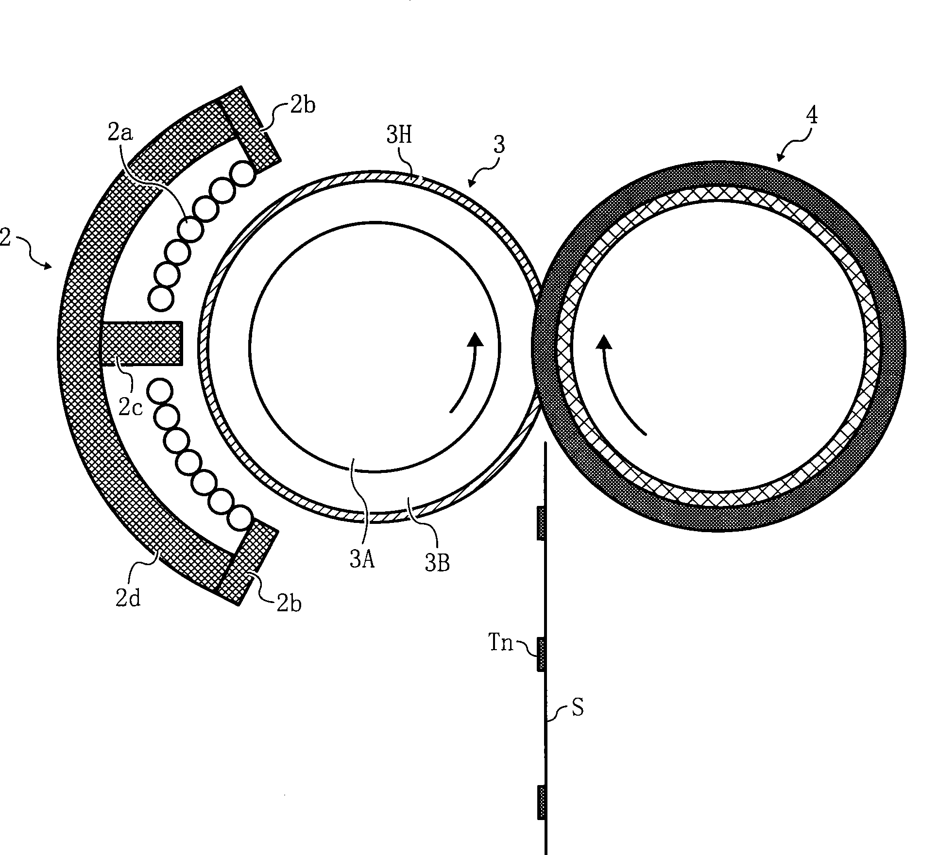
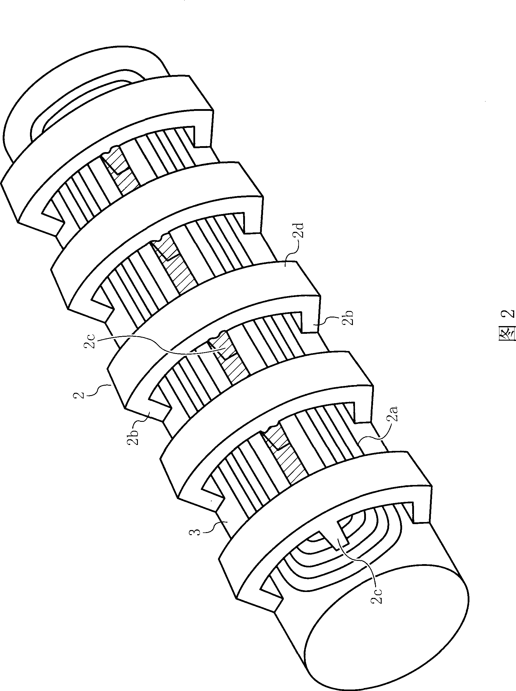
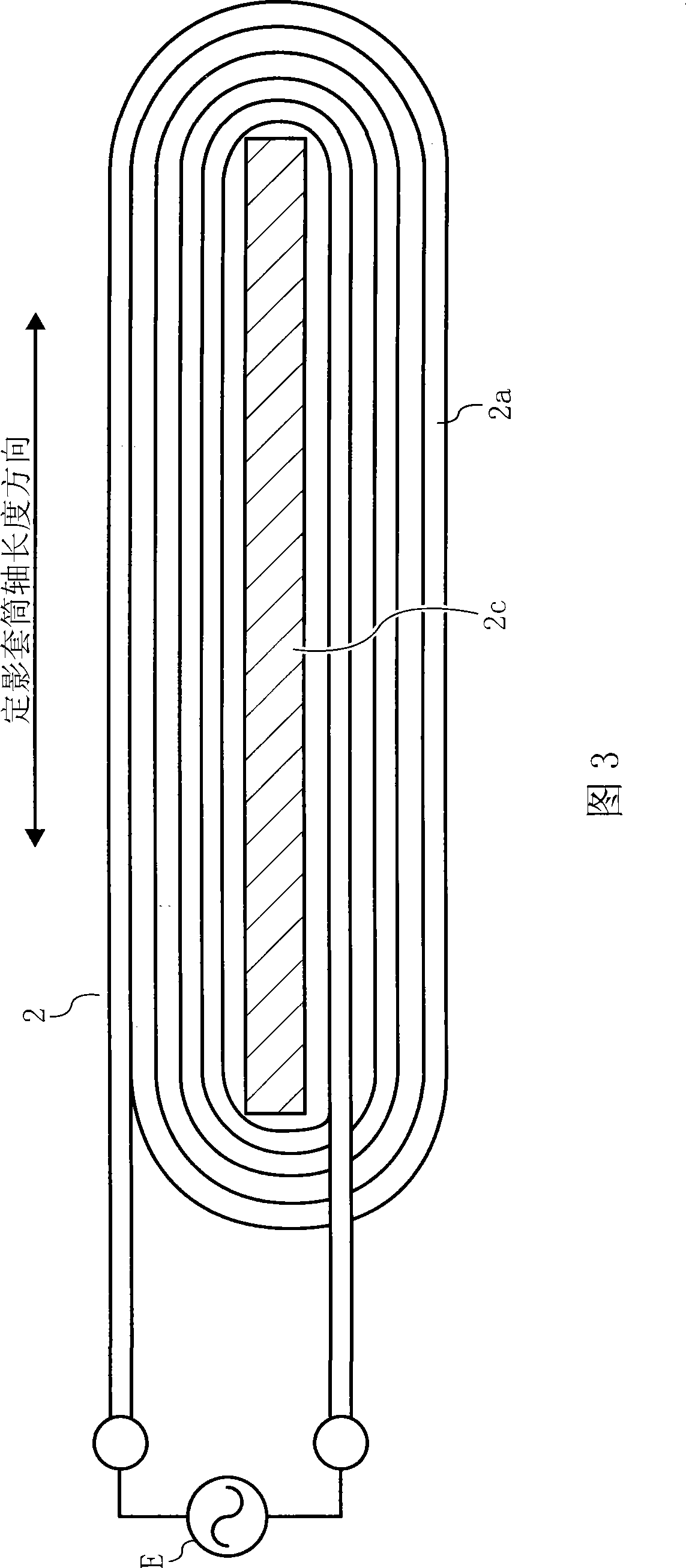
[0085] FIG. 8 shows the configuration and operation state of the magnetic flux generating unit 2 and the fixing roller 30 as a heat-generating rotating body. The configuration of the magnetic flux generating unit 2 is the same as that referred to in the above-mentioned reference example. figure 1 , Fig. 2, Fig. 3, Fig. 5 etc. described same. Regarding the fixing roller 30, the metal sleeve 3H is referred to as a reference example figure 1 , Figure 4 etc. described in the basic structure is the same.

[0086] In this example, in order to fix under the condition of high heating efficiency and use the amount of diamagnetic flux as a variable variable to increase the range of temperature settings for self-temperature control, the magnetic modulation alloy 3C adopts a Curie temperature higher than that of the existing fixing device. The material at the fusing temperature set in. Here, the existing fixing device is as the above-mentioned reference example in which the position ...

Embodiment 2

[0122] FIG. 15 shows the structure and operation of the magnetic flux generator 2 and the fixing roller 300 of the heat-generating rotor. The structure of the magnetic flux generating unit 2 is the same as the example shown in FIG. 8 . The metal sleeve 3H constituting the fixing roller 300 is also the same as that shown in FIG. 8 . The difference in structure between the metal sleeve 300 of this example and the metal sleeve 30 shown in FIG. The left shaft 6L is fixed to the left side plate 8L instead of the degaussing member 3A-1 and the magnetic core 3Q shown in FIG. 8 . In this way, even if the metal sleeve 3H is turned, the relative positions between the degaussing coils 3L, 3L and the exciting coil 2a are not changed.

[0123] The degaussing coils 3L, 3L are switched on or off by the switching element 16 to control the induced magnetic flux generated by the exciting coil 2a. Compared with embodiment 1, embodiment 2 does not need a device for moving the degaussing compon...

Embodiment 3

[0149] Figure 20 is a schematic diagram of a color image forming apparatus using the fixing device exemplified in the above embodiments. Of course, the present invention is neither limited to Figure 20 The image forming apparatus of the type shown is not limited to an apparatus for forming a color image, and an apparatus for forming a single image is also one of objects of the present invention.

[0150] This image forming apparatus includes a reading unit C, a discharged paper storage unit D, an image forming unit A, and a paper feeding unit B from above.

[0151] The reading part C is a device for reading the original placed on the original glass table C2. The original image is scanned by the reading walking body C1, and the image information is imaged on the CCD (Charge Coupled Devices) C4 through the lens C3. The image is captured It is converted into an electrical signal and sent to the exposure device A10 to provide image information data for exposure.

[0152] The ...


PUM


Abstract

The present invention relates to a fixing device using electromagnetic induction heating mode in an image forming apparatus, a heat-generating rotary member for the fixing device, and a temperature control method of the fixing device. The invention aims to provide a developing method, component and device, which can exert the characteristic of high-speed temperature rise by electromagnetic induction heating of the heat-generating rotary member, the risen temperature exceeding the Curie temperature of a magnetic shunt alloy. Specifically, the fixing device comprises a heat-generating rotary member including an exciting coil 2a, a metal sleeve 3H (including a heat-generating layer and a magnetic shunt alloy) and a degaussing member 3A-1. The magnetic shunt alloy layer is disposed between the exciting coil and the degaussing member. The heat-generating rotary member performs self-temperature control using a repulsive magnetic flux of the degaussing member caused by the magnetic flux of the exciting coil. The magnetic flux adjuster (magnet core 3Q and degaussing member 3A-1) adjusts an amount of the repulsive magnetic flux by adjusting the rotation position relative to the exciting coil 2a.

Description

technical field [0001] The present invention relates to an image forming apparatus such as a copying machine, a printer, a facsimile apparatus, a printing machine, and a multifunctional apparatus integrating these functions, and a fixing device using an electromagnetic induction heating method used in the image forming apparatus, and relates to rotation heating in the fixing apparatus. body and the temperature control method of the fixing device. Background technique [0002] In image forming devices such as copiers, printers, facsimile devices, printing machines, and multifunctional devices that combine these functions, visible images such as toner images on a latent image carrier are usually transferred to a sheet for recording. On the medium (paper), the image is output after being fixed. When the toner image passes through the fixing device, it is fixed on the sheet-shaped recording medium due to the melting and penetrating effect of heat and pressure. [0003] (A) Amo...

Claims


Application Information

Patent Timeline
Patent Type & Authority Applications(China)
IPC IPC(8): G03G15/20H05B6/36
CPCG03G15/2082G03G15/2042
Inventor 瀬尾洋
Owner RICOH KK
Learn More