
Multi-parameter self-confirming sensor and state self-confirming method thereof

A multi-parameter, sensor technology, applied in the field of sensors

Inactive Publication Date: 2010-12-29
HARBIN INST OF TECH
View PDF0 Cites 0 Cited by
  • Summary
  • Abstract
  • Description
  • Claims
  • Application Information

AI Technical Summary

Problems solved by technology

[0006] This invention aims to solve the problem that the existing multi-parameter sensor cannot evaluate its own state, and when a fault occurs, the fault type cannot be judged and the correct data cannot be obtained , and proposed a multi-parameter self-confirmation sensor and its state self-confirmation method

Method used


Image

  • Multi-parameter self-confirming sensor and state self-confirming method thereof
  • Multi-parameter self-confirming sensor and state self-confirming method thereof
  • Multi-parameter self-confirming sensor and state self-confirming method thereof

Examples


specific Embodiment approach 1

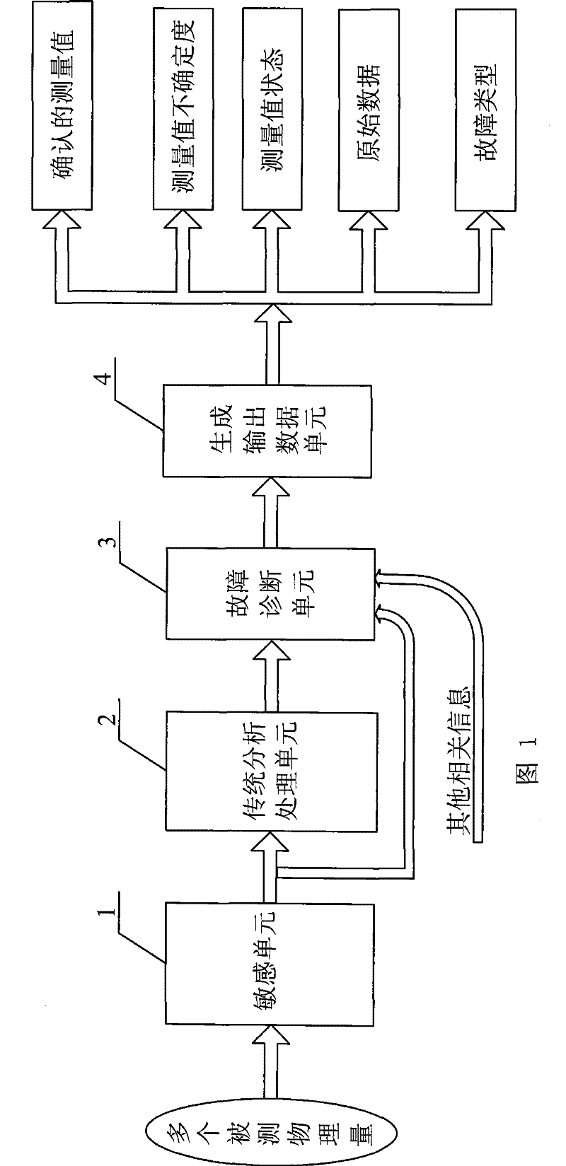
[0020] Specific embodiment one: this embodiment is described in conjunction with Fig. 1, and this embodiment is made up of sensitive unit 1, traditional analysis and processing unit 2, fault diagnosis unit 3 and generation output data unit 4; Sensitive unit 1 measures a plurality of measured physical quantities, sensitive The output end of the unit 1 is respectively connected to the input end of the traditional analysis processing unit 2 and an input end of the fault diagnosis unit 3, and the other two input ends of the fault diagnosis unit 3 respectively receive the signal data of the traditional analysis processing unit 2 and other related information, The output end of the fault diagnosis unit 3 is connected to the input end of the generating output data unit 4, and the output end of the generating output data unit 4 outputs various data.

[0021] Sensing unit 1 is a measuring unit that encapsulates sensitive elements for measuring multiple parameters in one sensor and can s...

specific Embodiment approach 2

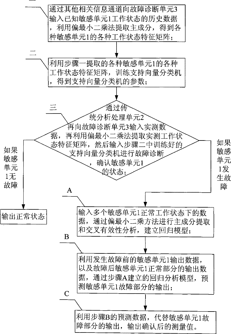
[0026] Specific implementation mode two: combination figure 2 Describe this embodiment, the steps of this embodiment are as follows:

[0027] Step 1: Input the historical data of the working state of the known sensitive unit 1 to the fault diagnosis unit 3 through other relevant information channels, use the partial least squares method to extract the principal components, and obtain various working state characteristic matrices of various sensitive units 1;

[0028] Step 2: Utilize the various working state feature matrices of the various sensitive units 1 extracted in step 1 to train the support vector classification machine, and obtain the parameters of the support vector classification machine;

[0029] Step 3: Input the measured data to the fault diagnosis unit 3 through the traditional analysis and processing unit 2, and then use the partial least squares method to extract the measured working state feature matrix, and then input the trained support vector classificatio...

specific Embodiment approach 3

[0033] Embodiment 3: The difference between this embodiment and Embodiment 1 lies in step 1. First, define the first parameter and the qth parameter data as the independent variable set X n×q , define the q+1th parameter and the mth parameter data as the data set Y n×(m-q) , n is the number of sample points, for X n×2 and Y n×1 Use the following formula (1) to standardize and get the corresponding X n×q Data set E 0 and the corresponding Y n×(m-q) Data set F 0 : (i=1, 2, ..., n; j = 1, 2, ..., m)

[0034] x ij * = x ij - x ‾ j s j - - - ( 1 )

[0035] That is, for each column of data, the mean value of the column is cu...


PUM


Abstract

The invention provides a multi-parameter self-validating sensor and a state self-validating method thereof, which relate to the sensor field and solve the problem of incapability of evaluating the self-state and the shortcomings of incapability of judging fault type and obtaining correct data when the fault occurs in the existing multi-parameter sensor. In the invention, a plurality of physical quantities to be measured pass through a sensitive component and a traditional analysis processing unit to obtain initial data; after passing through a fault diagnosis unit, the initial measuring data pass through an output data generating unit to obtain more rich output information. The multi-parameter sensor outputs more measured values of physical quantities than a single-parameter sensor, the correlation normally exists among the physical quantities, and the correlation is an important condition for the fault diagnosis and state validation. The invention can online evaluate working state and output data uncertainty, thus leading the system to clearly understand the online working state of the sensor and the credibility of output data; and the invention can diagnose the fault type and realize the data reconstruction when the fault occurs.

Description

technical field [0001] The invention relates to the field of sensors, in particular to a multi-parameter self-confirmation sensor and a state self-confirmation method thereof. Background technique [0002] Nowadays, the number and types of sensors used in various industrial occasions and equipment are increasing. As the source of information acquisition, the accuracy of the sensor's measurement data has a crucial impact on the system. [0003] In many applications, it is often necessary to detect multiple physical quantities at the same time. For example, in mines, it is often necessary to monitor temperature, humidity and methane at the same time to prevent danger. In closed environments such as submarines, it is often necessary to monitor temperature, humidity, wind speed, carbon monoxide, etc. to ensure The working environment is safe. [0004] With the advancement of technology, sensors are gradually developing towards multi-parameter sensors. Integrating several sens...

Claims


Application Information

Patent Timeline
Patent Type & Authority Patents(China)
IPC IPC(8): G01D5/00G01D18/00G06K9/62
Inventor 王祁赵树延宋凯冯志刚丁明理
Owner HARBIN INST OF TECH
Learn More