
A method for separating and imaging diffracted and reflected waves

An imaging method and technology of diffracted waves, which are applied in the fields of separated imaging of diffracted waves and reflected waves, extraction of diffracted wave signals and clear imaging of small geological anomalies or faults, can solve signal distortion, unclear imaging, diffracted wave Weak signal and other problems, to achieve the effect of clear diffraction wave signal imaging

Active Publication Date: 2016-08-10
CHINA PETROLEUM & CHEM CORP +1
View PDF0 Cites 0 Cited by
  • Summary
  • Abstract
  • Description
  • Claims
  • Application Information

AI Technical Summary

Problems solved by technology

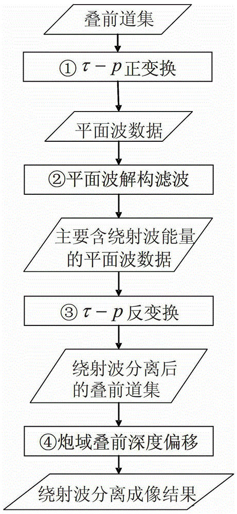
[0003] Aiming at the problem of weak diffraction wave signal and unclear imaging in pre-stack migration imaging, the present invention provides a method for separating imaging of diffraction wave and reflected wave, and performs three-dimensional time domain τ-p Forward and inverse transformation, the plane wave domain diffraction wave data after plane wave deconstruction and filtering are completely converted into prestack gathers, and then the diffraction wave information is imaged in shot domain prestack migration, thus avoiding two-dimensional τ-p forward and inverse transformation signal distortion problem

Method used


Image

  • A method for separating and imaging diffracted and reflected waves
  • A method for separating and imaging diffracted and reflected waves
  • A method for separating and imaging diffracted and reflected waves

Examples


Embodiment 1

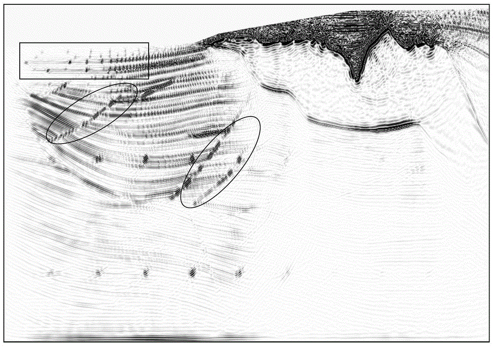
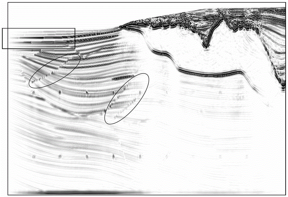
[0046] Embodiment 1: Diffraction wave separation imaging processing is performed on the sigsbee model data. figure 2 is the diffraction wave imaging result obtained by the method of the present invention, image 3 is the result of conventional migration imaging without wavefield separation. Compared figure 2 and image 3 It can be seen that the results of the implementation of the present invention make the imaging of diffraction points (marked by rectangles in the figure) and faults (marked by ellipses in the figure) clearer.

Embodiment 2

[0047] Embodiment 2: Using the actual data of a western region to compare the effect of three-dimensional time domain τ-p forward and reverse transformation and two-dimensional τ-p forward and reverse transformation. Pic 4-1 is the original prestack gather, Figure 4-2 is the gather after two-dimensional τ-p positive and negative transformation, Figure 4-3 It is a gather that undergoes three-dimensional τ-p forward and reverse transformation by using the method of the present invention. Comparing the three figures, it can be seen that the two-dimensional τ-p positive and negative transformation results show a short flat axis phenomenon, Figure 4-2 and Pic 4-1 The difference is very large, indicating that there is a data distortion problem in the forward and reverse transformation; after the three-dimensional τ-p forward and reverse transformation, Figure 4-3 and Pic 4-1 It is basically consistent, indicating that the data is well restored through the positive and neg...


PUM


Abstract

The invention provides a diffracted wave and reflected wave separating and imaging method and belongs to the field of seismic data imaging processing. The method comprises the following steps: (1) conducting three-dimensional tau-p positive transformation on each gather in each line to obtain plane wave data d(py, px, y, x and tau); (2) adopting plane wave domain deconstruction filtering to process the plane wave data d (py, px, y, x and tau) output in the step (1) to obtain plane wave data dr(py, px, y, x and tau) mainly containing diffracted wave energy; (3) extracting three-dimensional tau-p domain data corresponding to each gather from the plane wave data dr(py, px, y, x and tau) mainly containing diffracted wave energy obtained in the step (2), obtaining the shot intersecting coordinate of each gather from an original gather, and then conducting three-dimensional tau-p inverse transformation on the three-dimensional tau-p domain data to obtain prestack gathers after wave field separation; (4) conducting shot-domain prestack depth migration on the prestack gathers after wave field separation output in the step (3) to obtain a diffracted wave separating and imaging result. With adoption of the method, diffracted wave signal extraction and clear imaging of small geologic abnormal bodies or faults are realized.

Description

technical field [0001] The invention belongs to the field of imaging processing of seismic data, and in particular relates to a method for separating and imaging diffraction waves and reflection waves, which is used for diffraction wave signal extraction and clear imaging of small geological anomalies or faults. Background technique [0002] Due to the weak energy of diffraction wave signals from small geological anomalies in seismic records, accurate imaging usually requires wave field separation or diffraction wave extraction before imaging. The existing plane wave domain deconstruction filtering diffraction wave and reflection wave separation imaging method is an effective method, which includes τ-p transformation, co-p plane wave data sorting, plane wave domain deconstruction filtering, plane wave prestack migration and other steps . However, in order to make the imaging effect of the plane wave prestack migration comparable to that of the traditional shot domain presta...

Claims


Application Information

Patent Timeline
Patent Type & Authority Patents(China)
IPC IPC(8): G01V1/28
Inventor 段心标方伍宝吕秋玲王鹏燕宋林
Owner CHINA PETROLEUM & CHEM CORP
Learn More