
Double-phase opposition giant magnetostriction self-sensing drive direct force feedback servo valve

A giant magnetostrictive and self-sensing technology, applied in the field of servo control, can solve the problems of difficult to meet the requirements of the working bandwidth of the motor converter, poor anti-interference ability, and low energy density, so as to improve the motion accuracy and valve performance. The effects of control accuracy, system stability, and short response time

Inactive Publication Date: 2009-03-11
BEIJING UNIV OF TECH
View PDF0 Cites 13 Cited by
  • Summary
  • Abstract
  • Description
  • Claims
  • Application Information

AI Technical Summary

Problems solved by technology

[0002] At present, direct-acting electro-hydraulic servo valves are all driven by electromagnetic torque motors. Due to the complex structure, large volume and weight, narrow working frequency bandwidth, low energy density, low resolution, and poor anti-interference ability of this driving method, it is difficult to meet the requirements. The requirements of modern industry for fluid control systems, the application is very limited
With the development of direct-acting electro-hydraulic servo valves in the direction of high pressure, large flow, high frequency response, high and low temperature environment adaptability, and anti-interference, modern industries such as precision position control, aerospace and marine operations, and deep-sea exploration and other fields require ultra-high speed. The demand for direct-acting electro-hydraulic servo valves, the working bandwidth of traditional force (torque) motor converters is difficult to meet the requirements (generally less than 400Hz), research and development of slide valves with new drive technology and new drive structure has become a hydraulic Frontier subject of servo control technology development

Method used


Image

  • Double-phase opposition giant magnetostriction self-sensing drive direct force feedback servo valve
  • Double-phase opposition giant magnetostriction self-sensing drive direct force feedback servo valve
  • Double-phase opposition giant magnetostriction self-sensing drive direct force feedback servo valve

Examples


Embodiment Construction

[0023] The present invention will be further described below in conjunction with accompanying drawing:

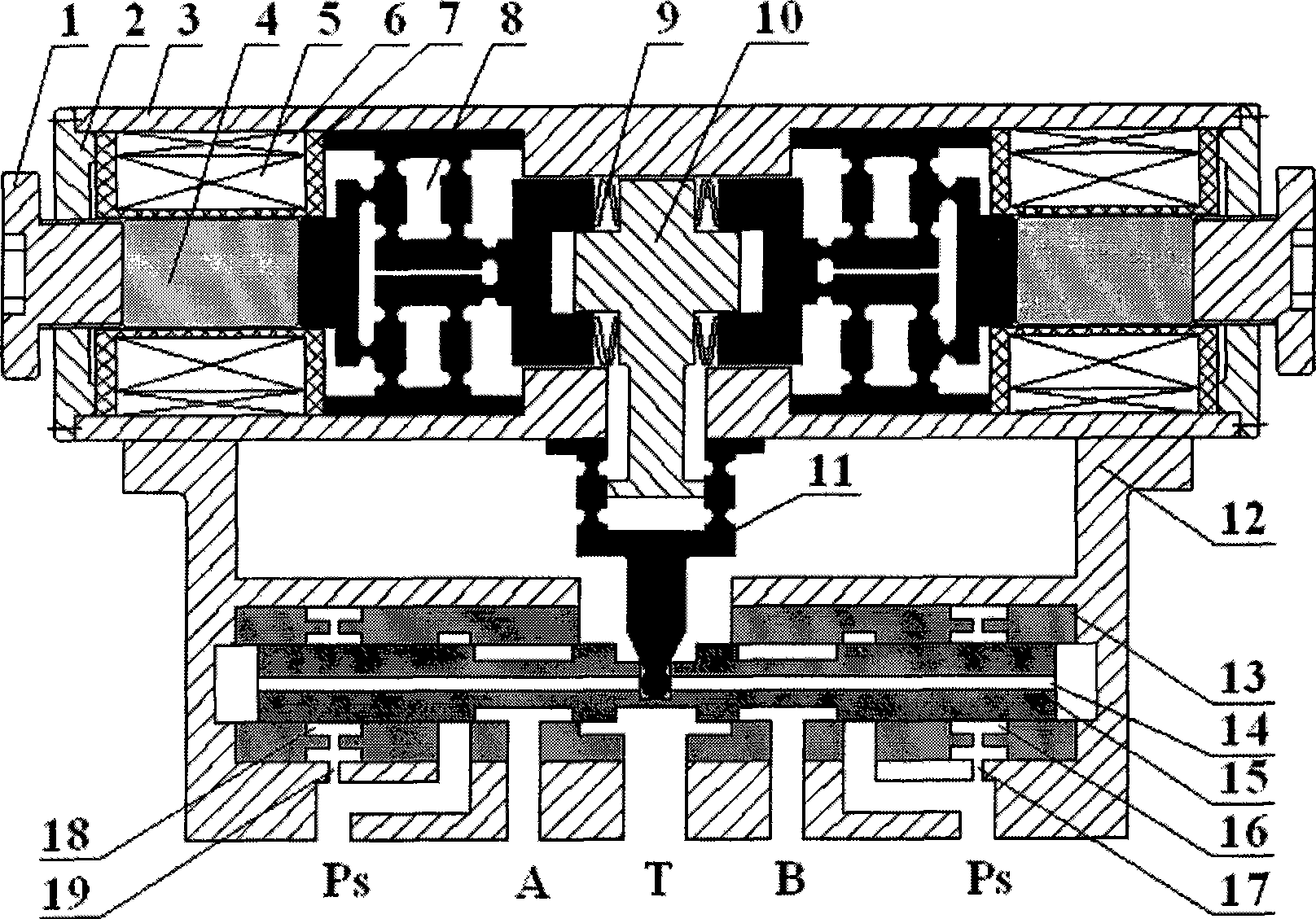
[0024] This embodiment is composed of two parts: the upper part is a double-phase opposing giant magnetostrictive self-sensing driver; the lower part is a power stage slide valve.

[0025]The function of the driver is to convert the input current signal into the deflection of the flexible hinged push rod. It includes an outer casing, an inner casing and an output assembly 10. The casing includes a casing 3 and end caps 2 fixed at both ends of the casing 3 . The inner sleeve includes an adjusting screw 1, a coil frame 7, a giant magnetostrictive rod 4, a driving coil 5, a bias coil 6, a coil frame 7, and a micro-displacement amplification mechanism 8, and forms a closed magnetic circuit, so that the magnetic flux generated in the coil Basically, they are confined in the magnetic circuit composed of magnetic materials, and the magnetic flux leakage is very small, which not ...


PUM


Abstract

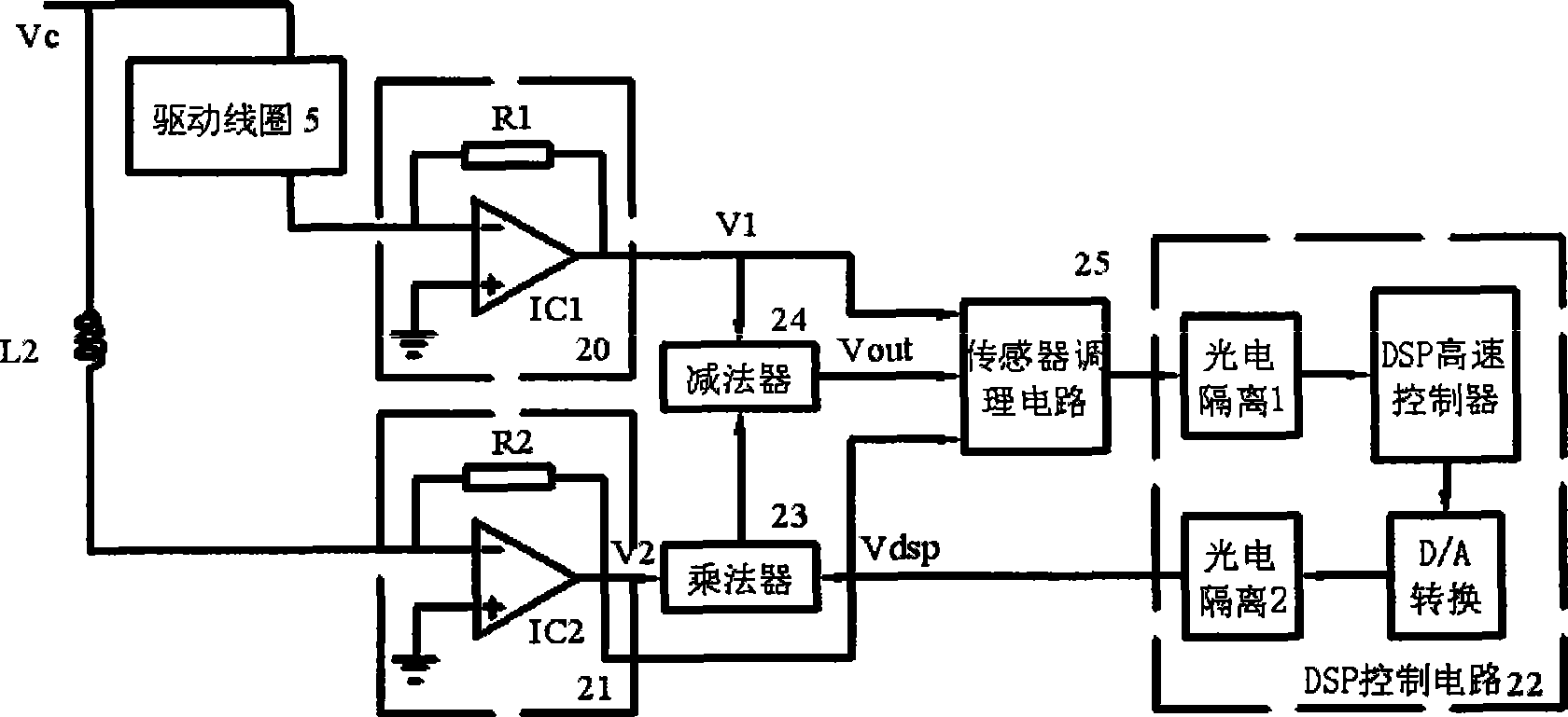
The invention relates to a dual-phase butting ultra-magnetostrictive self-sensing driving direct force feedback servo valve, belonging to the servo control field. Two single-magnetostrictive drivers with completely identical structure and dimension are symmetrically arranged at two sides of an output component by a butterfly spring, thus forming the self-sensing driver of dual-butting structure and using a single-DOF flexible hinge mechanism for realizing the amplification and transmission of output displacement. A direct force feedback servo valve is formed by a flexible hinge pushing rod with displacement amplification function and a power-step sliding valve. By virtue of the self-sensing function of the driver, a dynamic balance separation signal circuit controlled by a DSP singlechip detects the output signals in real-time, realizes the real-time control and precise positioning on the driving object, can be used for driving control and sensing detection system of precise displacement, velocity and accelerator and force, integrates the driving and sensing detection function into a whole body, and is especially suitable to water pressure transmission and control field.

Description

technical field [0001] The invention relates to a double-phase opposed giant magnetostrictive self-sensing drive direct force feedback servo valve, which is a hydraulic control element integrating driving and sensing detection functions, has high dynamic response performance, and is especially suitable for application It is used in deep sea exploration and underwater operation, and belongs to the technical field of servo control. Background technique [0002] At present, direct-acting electro-hydraulic servo valves are all driven by electromagnetic torque motors. Due to the complex structure, large volume and weight, narrow working frequency bandwidth, low energy density, low resolution, and poor anti-interference ability of this driving method, it is difficult to meet the requirements. The requirements of modern industry for fluid control systems are greatly restricted. With the development of direct-acting electro-hydraulic servo valves in the direction of high pressure, ...

Claims


Application Information

Patent Timeline
IPC IPC(8): F16K31/02F16K31/72F15B13/044
Inventor 王新华王思民李伟肖锋郑健
Owner BEIJING UNIV OF TECH
Learn More