
Digital gain control method and circuit

A digital gain and control method technology, applied in the direction of gain control, amplification control, electrical components, etc., can solve the problems of chip cost increase, large resistance area, etc., and achieve the effect of ensuring monotonicity and reducing chip area

Inactive Publication Date: 2009-02-25
RDA MICROELECTRONICS BEIJING
View PDF0 Cites 16 Cited by
  • Summary
  • Abstract
  • Description
  • Claims
  • Application Information

AI Technical Summary

Problems solved by technology

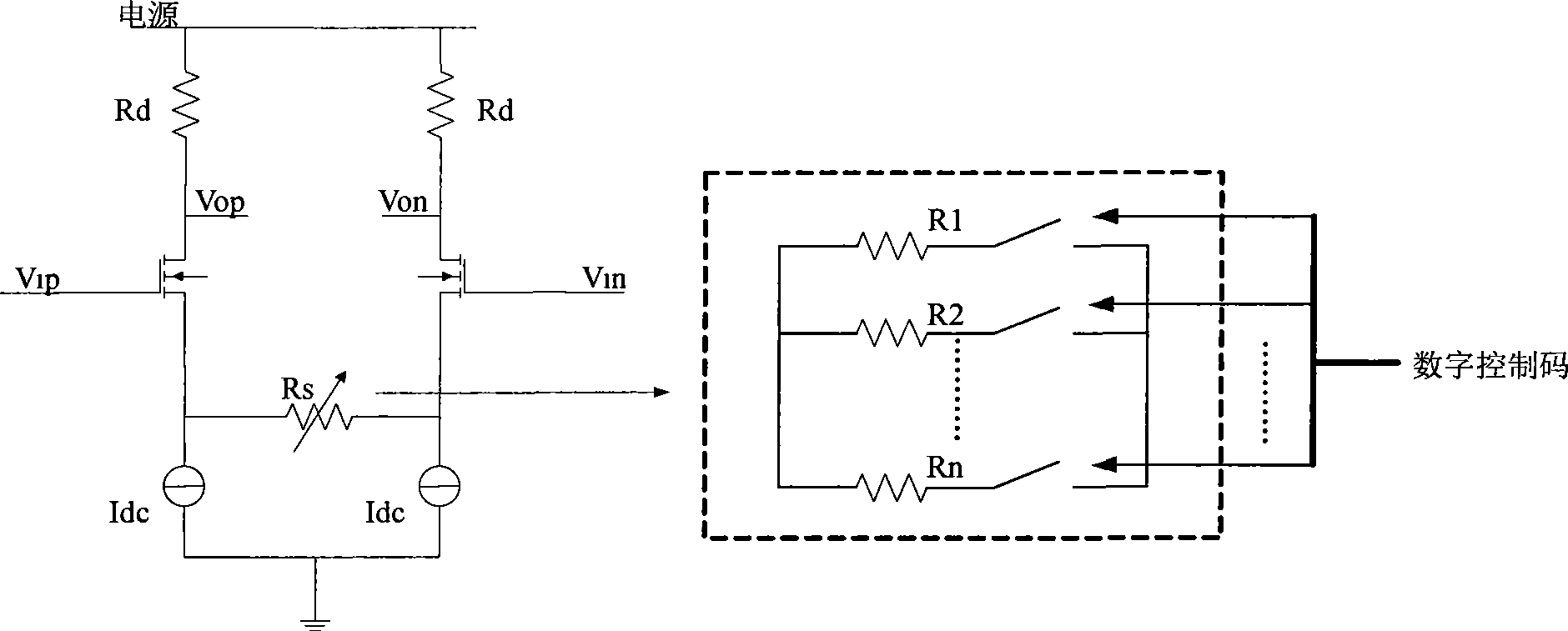
[0004] In short, in order to meet the requirements of wide-range and high-precision gain control at the same time, implementing a digitally controlled gain amplifier in the form of a resistor array will bring a larger resistor area, which will increase the cost of the chip

Method used


Image

  • Digital gain control method and circuit
  • Digital gain control method and circuit
  • Digital gain control method and circuit

Examples


Embodiment Construction

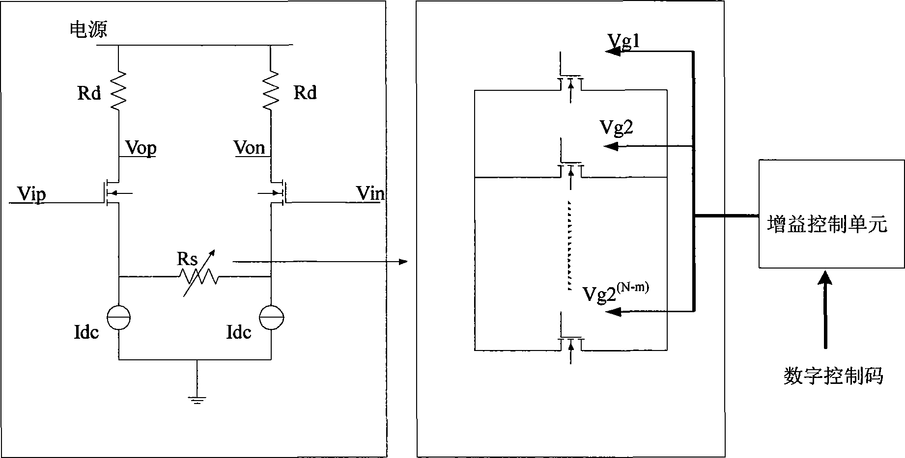
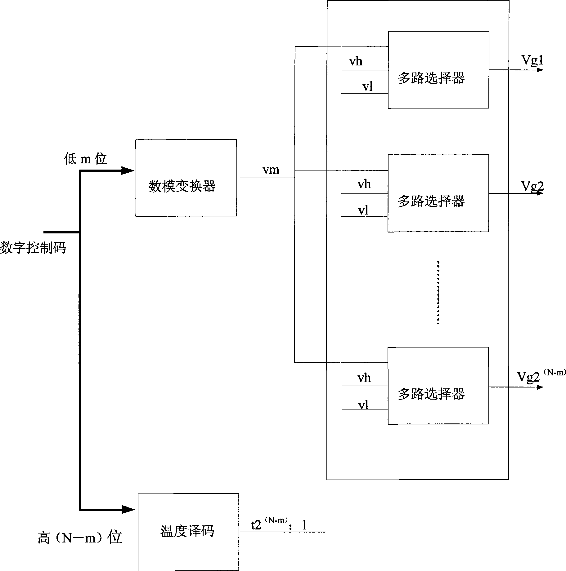
[0018] A specific embodiment of the present invention is as figure 2 As shown, the variable resistor Rs in the variable gain amplifier is implemented with an array of MOS (metal oxide semiconductor) transistors, the source and drain of each transistor are connected in parallel, and the relationship between the on-resistance and the gate voltage of the transistor is used to determine control resistor value. The individual gate voltages of the transistor array will be generated by the gain control block; image 3 The gain control module shown uses an analog-to-digital converter to convert the low m bits of the N-bit binary gain digital control code into an output control voltage with a resistive digital-to-analog converter; and the high (N-m) bits are used for thermometer decoding , becomes a 2 (N-m) The thermometer code of one symbol, the value of m is determined according to the adjustment range and the adjustment accuracy needs, such as the number of digits of the binary g...


PUM


Abstract

The invention discloses a digital gain controlling means. An N-bit binary digit gain control code controls the resistance of a variable resistor in a variable gain amplifier for the gain adjustment of the variable gain amplifier; an MOS transistor array is used as the variable resistor; the variable resistance value is controlled by utilizing the relation between the on-resistance between source electrodes and drain electrodes of transistors and the voltage of grid electrodes; a gain control module generates the grid electrode voltage of each transistor in the MOS transistor array according to the N-bit binary digit gain control code; a circuit for realizing the digital gain controlling means is also disclosed. By adopting the digital gain controlling means and the circuit, an integrated circuit is led to have smaller chip area when satisfying the gain control demand of large range and high precision.

Description

technical field [0001] The invention relates to a wireless transceiver integrated circuit technology, in particular to a digital gain control method and circuit. Background technique [0002] In modern wireless communication transceiver integrated circuits, gain adjustment is an essential function due to the strict requirements on the transmit power and the uncertainty of the receive power. Gain adjustment can be realized by analog and digital methods, and the digital method has the characteristics of simple implementation and good performance because it can use the advanced digital signal processing circuit integrated in the transceiver, which is in line with the trend of today's digital wireless transceivers. Digital control gain adjustment uses digital signals to control the gain of the amplifier. In many applications, a large gain control range (such as 40dB~60dB) and high adjustment accuracy (such as 0.1dB~0.5dB) are often required. In addition, since the gain control ...

Claims


Application Information

Patent Timeline
Patent Type & Authority Applications(China)
IPC IPC(8): H03G3/00H03G7/06H04B1/40
Inventor 杜定坤魏述然
Owner RDA MICROELECTRONICS BEIJING
Learn More