
Pulling switch for electric power

A switch and power supply technology, applied in the direction of electric switches, circuits, electrical components, etc., can solve problems such as unstable work, poor contact of switches, and easy to be pulled off

Inactive Publication Date: 2010-06-30
邓玉祥
View PDF0 Cites 0 Cited by
  • Summary
  • Abstract
  • Description
  • Claims
  • Application Information

AI Technical Summary

Problems solved by technology

The main problems of this structure are: the pull wire is not pulled in a straight line, and it is easy to be pulled off, which brings unnecessary troubles to the use; in addition, it is unstable when working, especially in the case of a relatively bad working environment, such as violent bumps. , vibration, etc., often cause the switch to lose its function due to poor contact

Method used


Image

  • Pulling switch for electric power
  • Pulling switch for electric power
  • Pulling switch for electric power

Examples


Embodiment Construction

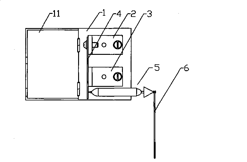
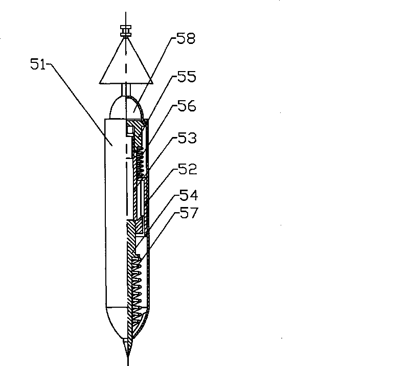
[0011] Combine below figure 1 figure 2 The specific embodiment will further describe the present invention.

[0012] The power pull switch includes a switch box 1, the switch box 1 is rotated and installed with a safety box cover 11, and the first terminal 2 and the second terminal 3 are fixedly installed in the switch box 1, and one end is fixedly installed on the first terminal 2 The reed 4 on the top is fixed in the switch box 1 and one end extends out of the telescopic mechanism 5 outside the switch box 1. The reed 4 contacts one end of the telescopic mechanism 5 through the second terminal post 3, and the outer end of the telescopic mechanism 5 is connected to the telescopic mechanism 5. There is a backguy 6 through which the expansion and contraction of the telescopic mechanism 5 is controlled, and the telescopic mechanism 5 controls the reed 4 through telescoping, so that the reed 4 is in contact with or disconnected from the second terminal 3, thereby closing the cir...


PUM


Abstract

The invention relates to a power supply pull-board switch, which comprises a switch box, a box cover, a first terminal, a second terminal, a spring leaf and a telescopic mechanism. The spring leaf is in contact with one end of the telescopic mechanism through the second terminal; the telescopic mechanism comprises a guide shell body, a guide pipe, a guide sleeve, a thimble, a compression shaft head, a reset spring, a universal compression cap, a compression spring and a reset spring; the cap edge of the universal compression cap is in contact with the inner wall of the guide shell body; and the cap body thereof is positioned outside the guide shell body. In the invention, the direct contact of a pull wire of the switch with the spring leaf is replaced by the manner that the pull wire is led out of one end of the telescopic mechanism or the universal compression cap is directly turned to control the expansion of the telescopic mechanism, thereby achieving the pulling and turning purposes and solving a series of problems caused by the easy breaking of the power supply pull wire, and the like. In addition, the telescopic mechanism is perpendicular to the spring leaf, so as to ensure the on-off status of the spring leaf and the terminals; when the thimble pushes against the spring leaf or is released, thereby enabling the switch to be operated normally and stably in more complex environment.

Description

technical field [0001] The invention relates to a switch, in particular to a pull switch for a power supply. Background technique [0002] In the prior art, the general structure of the known pull switch is that the pull wire pulls a reed that rotates in one direction, and is reset by the spring. When pulled once, the position of the reed short-circuits the two terminals, the circuit is connected, and the reed is pulled once again. The position of the chip is that the two terminals are disconnected and the circuit is cut off. The main problems of this structure are: the pull wire is not pulled in a straight line, and it is easy to be pulled off, which brings unnecessary troubles to the use; in addition, it is unstable when working, especially in the case of a relatively bad working environment, such as violent bumps. , vibration, etc., often cause the switch to lose its function due to poor contact. Contents of the invention [0003] The purpose of the present invention ...

Claims


Application Information

Patent Timeline
Patent Type & Authority Patents(China)
IPC IPC(8): H01H17/16
Inventor 范伟峰郭永平郑贞芳张芹芹邓玉祥
Owner 邓玉祥
Learn More