Robot system
A robot system and robot technology, applied in the field of robot systems, can solve problems such as the inability to clamp objects and the inability to judge the position command of the robot arm, and achieve the effect of reducing the risk of crushing or slipping
- Summary
- Abstract
- Description
- Claims
- Application Information
AI Technical Summary
Problems solved by technology
Method used
Image

Examples
Embodiment 1
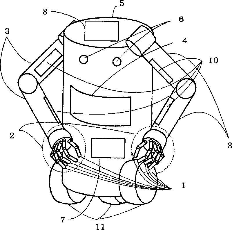
[0070] figure 1 It is an overall configuration diagram showing the configuration of a robot implementing the present invention.
[0071] exist figure 1 Among them, 1 is the hand force sensor, 2 is the hand, 3 is the arm, 4 is the torso force sensor, 5 is the torso, 6 is the camera, 7 is the robot control part, 8 is the image processing part, 10 is the arm Department force sensor, 11 is moving mechanism.
[0072] Below, use figure 1 The overall configuration of a robot embodying the present invention will be described.
[0073] The trunk 5 of the robot includes two arm parts 3 and a trunk force sensor 4 for measuring the load on the trunk 5 is arranged. Each arm part 3 has a hand part 2 at the front end. The hand 2 includes five fingers having the hand force sensor 1 at the tip. Two cameras 6 installed on the torso 5 of the robot measure the shape of the gripped object. The robot control unit 7 controls the movement of the arm unit 3 . The image processing unit 8 of ...
Embodiment 2
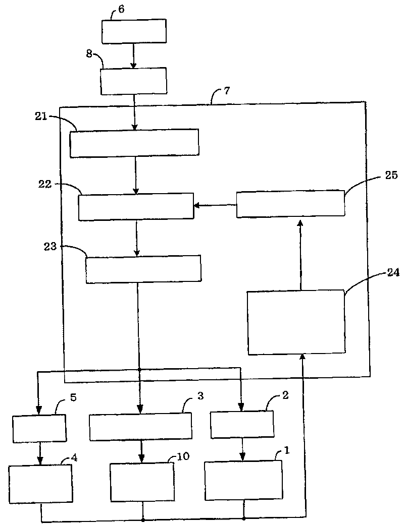
[0099] Figure 10 is a configuration diagram showing a robot system according to a second embodiment of the present invention.
[0100] exist Figure 10 Among them, 9 is a storage unit. Additionally, with figure 1 The same explanatory notation indicates the same as figure 1 The description of the same constituent elements is omitted.
[0101] The difference between this embodiment and the first embodiment is that the robot system of this embodiment is equipped with, when the clamped object is clamped, the inherent attribute information related to the clamped object, that is, the size, shape, and mass of the clamped object The storage unit 9 stores and maintains one or more pieces of data related to the gripping object, such as color depth and data related to the gripping method, as gripping object data.
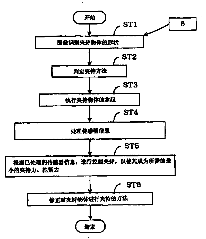
[0102] Fig. 11 is a flowchart illustrating the operation of the robot system according to the second embodiment of the present invention. In addition, the same step S...
Embodiment 3
[0111] The structure of the robot system in this embodiment is the same as that of the first embodiment figure 1 , figure 2 are the same, so its description is omitted.
[0112] The difference between the robot system of this embodiment and the first embodiment is that this embodiment places the operation of determining the gripping position based on the size and shape of the gripped object obtained from the image of the camera 6, that is, step ST41, in the first embodiment. between step ST11 and step ST12.
[0113] Fig. 12 is a flowchart illustrating the operation of the robot system according to the third embodiment of the present invention. In addition, the same step ST numbers as in FIG. 4 showing the first embodiment indicate the same processing contents as in FIG. 4 .
[0114] Next, the operation in the robot system of this embodiment will be described with reference to FIG. 12 .
[0115] In step ST11, the size and shape of the gripping object are calculated using ...
PUM
 Abstract
Description
Claims
Application Information
 - R&D
- Intellectual Property
- Life Sciences
- Materials
- Tech Scout
- Unparalleled Data Quality
- Higher Quality Content
- 60% Fewer Hallucinations
Browse by: Latest US Patents, China's latest patents, Technical Efficacy Thesaurus, Application Domain, Technology Topic, Popular Technical Reports.
© 2025 PatSnap. All rights reserved.Legal|Privacy policy|Modern Slavery Act Transparency Statement|Sitemap|About US| Contact US: help@patsnap.com