
Optical-information reproducing system

A regenerative system and optical information technology, applied in the directions of information arrangement, information storage, recording information storage, etc., can solve the problems of increased speed change in the inner and outer peripheral areas, tracking deviation, and reduced tracking of optical read heads, etc., to achieve increased Effects of gain margin, improved tracking, and reduced tracking deviation

Inactive Publication Date: 2009-02-04
TAIYO YUDEN KK
View PDF1 Cites 0 Cited by
  • Summary
  • Abstract
  • Description
  • Claims
  • Application Information

AI Technical Summary

Problems solved by technology

However, if you increase the gain in the low band, you cannot ignore the higher order resonances of the read
If the gain of the low band is increased, the following problem will occur, that is, the difference (gain margin) between the gain of a certain reference frequency (around the crossover frequency of the servo) and the gain of the high-order resonance peak becomes smaller or negative, and the optical read head The tracking performance is reduced, resulting in tracking deviation
For example, in an optical information recording medium that reproduces information by rotating at a fixed speed of 3.49 m / s like DVD-R, the rotational speed of the outer peripheral region (with a radius of about 58 mm) is about 9.6 rps. The rotation speed in the peripheral area (with a radius of about 23mm) is about 24.2rps, and the variation in the rotation speed on the inner and outer peripheral areas increases, so the above-mentioned problems are likely to occur

Method used


Image

  • Optical-information reproducing system
  • Optical-information reproducing system
  • Optical-information reproducing system

Examples


Embodiment Construction

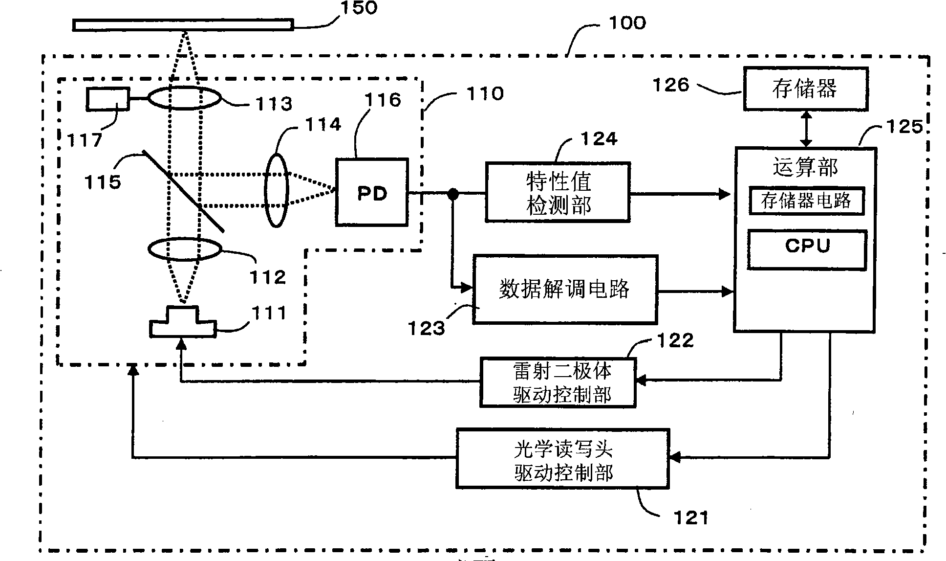
[0044] Below, use figure 1A functional block diagram of a recording device according to an embodiment of the present invention will be described. The optical disk playback device 100 includes: a memory 126, which stores data in processing, data of processing results, reference data in processing (such as policy data corresponding to each medium ID (identification, identification)); A CPU (Central processing unit, central processing unit) for computing and a memory circuit for recording a program for data processing; a laser diode drive control unit 122, which controls the laser light for recording and the laser light for reproduction; the data demodulation circuit 123, for The output reproduction signal carries out specific decoding processing; The characteristic value detection part 124, it detects the reproduction signal and detects the signal of focusing, tracking, swinging etc.; Optical pickup 110; Optical pickup drive control part 121, it controls from The direction of ...


PUM

PropertyMeasurementUnit
diameteraaaaaaaaaa
thicknessaaaaaaaaaa
thicknessaaaaaaaaaa

Abstract

An optical-information reproducing system is provided, in which the tracking capability of an optical pickup can be increased, and in which the number of occurrences in which the optical pickup fails to track a groove can be reduced, by increasing a gain margin and by ensuring the gain margin. In the optical-information reproducing system, an optical-information recording medium 150 is rotated at a fixed linear velocity of about 3.49 m / s, and the optical pickup 110 is caused to track the groove 152 to irradiate the groove with laser light, whereby information recorded on the optical-information recording medium can be reproduced. A higher-order resonance frequency of the optical pickup that is generated when the optical pickup 110 is caused to track the groove 152 can be made lower than a wobble frequency that is reproduced using the groove 152 without performing rotation control on the optical-information recording medium 150.

Description

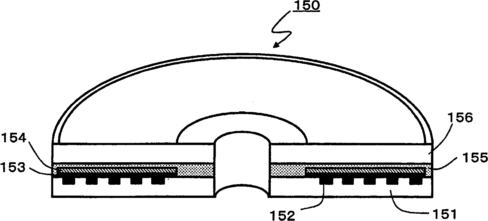
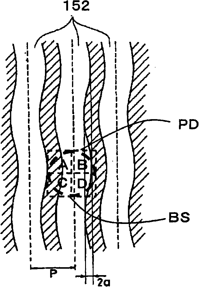
technical field [0001] The present invention relates to an optical information reproducing system for reproducing information recorded in an optical information recording medium, and includes an optical information recording medium and an optical disc device. Background technique [0002] Recordable CD (Compact Disc, optical disc) (so-called CD-R (Compact Disc-Recordable)) has the following structure, that is, one side of a light-transmitting substrate with a diameter of 12 cm and a thickness of 1.2 mm is provided with a spiral concave The groove is used to guide the optical head and record information, and a recording layer and a reflective layer are sequentially formed on the surface where the groove is formed. On this groove, a wobble track (wobble) is formed so that correct position information can be confirmed, and the wobble track repeatedly meanders at a fixed periodic frequency along the advancing direction of the groove. This groove is also called a magnetic track....

Claims


Application Information

Patent Timeline
Patent Type & Authority Applications(China)
IPC IPC(8): G11B7/09G11B7/007G11B7/24
CPCG11B7/0935
Inventor 清水宏郎
Owner TAIYO YUDEN KK
Learn More