
Electric power steering device

A technology of electric power steering and steering column, which is applied in the direction of electric steering mechanism, electromechanical device, steering column, etc. It can solve the problems of adding electric power steering device, poor connector connection workability, and insufficient heat dissipation effect, etc. Heat capacity, the effect of improving the heat dissipation effect

Inactive Publication Date: 2009-01-21
NSK LTD
View PDF5 Cites 20 Cited by
  • Summary
  • Abstract
  • Description
  • Claims
  • Application Information

AI Technical Summary

Problems solved by technology

[0006] However, in the conventional examples described in the aforementioned Patent Documents 1 to 4, since the CPU, FETs, capacitors, power relays, etc. are arranged on one control board, heat-generating components such as FETs and capacitors are mixed with the CPU, etc., which are afraid of temperature rise. Therefore, the housing for accommodating the control substrate is enlarged, and the heat generated by the heat-generating components is likely to fill the housing for accommodating the control substrate. In addition, although the FET is mounted on the support substrate as a heat sink, due to the thermal mass of the support substrate ( heatmass) is small, so there is an unsolved problem that it cannot exert sufficient heat dissipation effect
[0007] In addition, in the conventional examples described in the aforementioned Patent Documents 1 to 4, the electric power steering apparatus has a structure in which a controller for accommodating drive control of the motor is formed between the motor case of the rack case and the steering gear case. Therefore, the connector for external power supply or input and output signals must be arranged close to the steering gear box, and water droplets or dust are easy to intrude at the connector position, and since the connector is located near the steering gear box , so the direction of the connector connection is uniquely determined, and there is an unsolved problem that the workability of the connector connection is poor.
[0008] In addition, in the conventional example described in the above-mentioned Patent Document 5, the worm gear mechanism, the magnetic sensor, and the control board are sequentially arranged in the case and the cover, so that the axial length of the case and the cover becomes longer, and the control board is located near the steering column. Therefore, there are unsolved problems as follows: in order to ensure a predetermined collapse stroke for the steering column, it is necessary to increase the overall length of the electric power steering device, and in order to realize the miniaturization of the electric power steering device, the predetermined stroke cannot be ensured. Crushing stroke

Method used


Image

  • Electric power steering device
  • Electric power steering device
  • Electric power steering device

Examples


Embodiment Construction

[0064] Embodiments of the present invention will be described below with reference to the drawings.

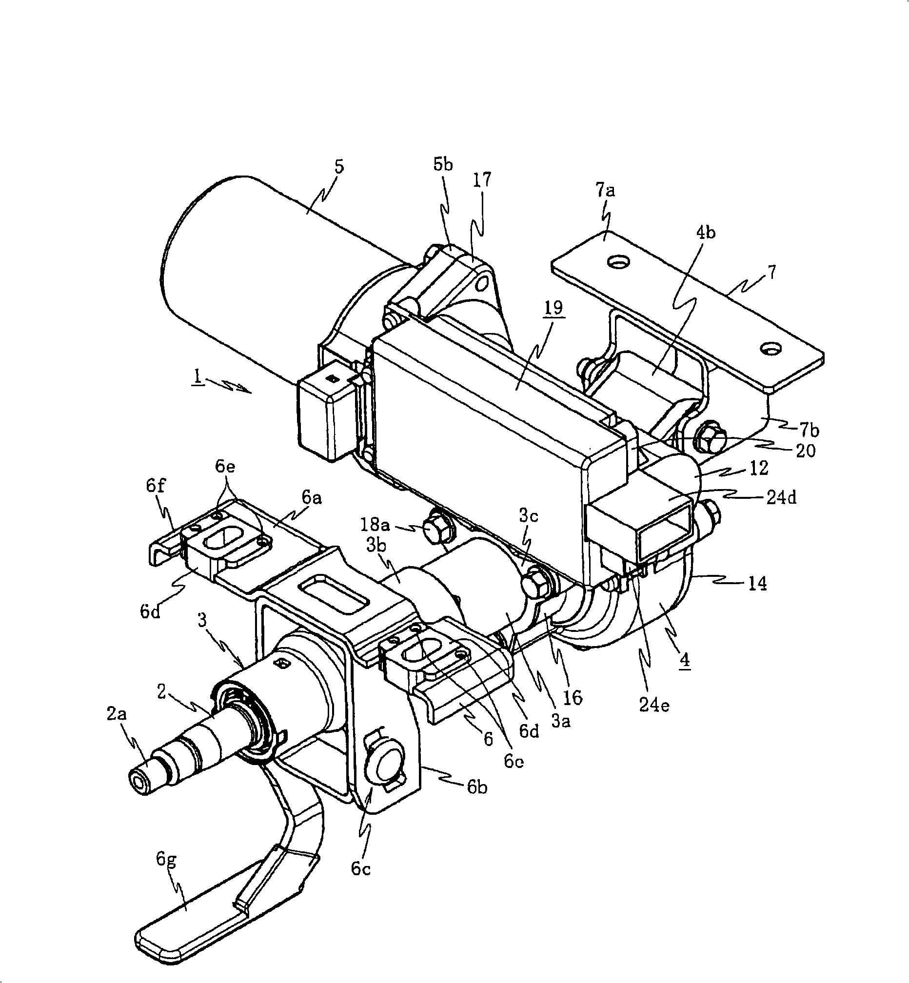
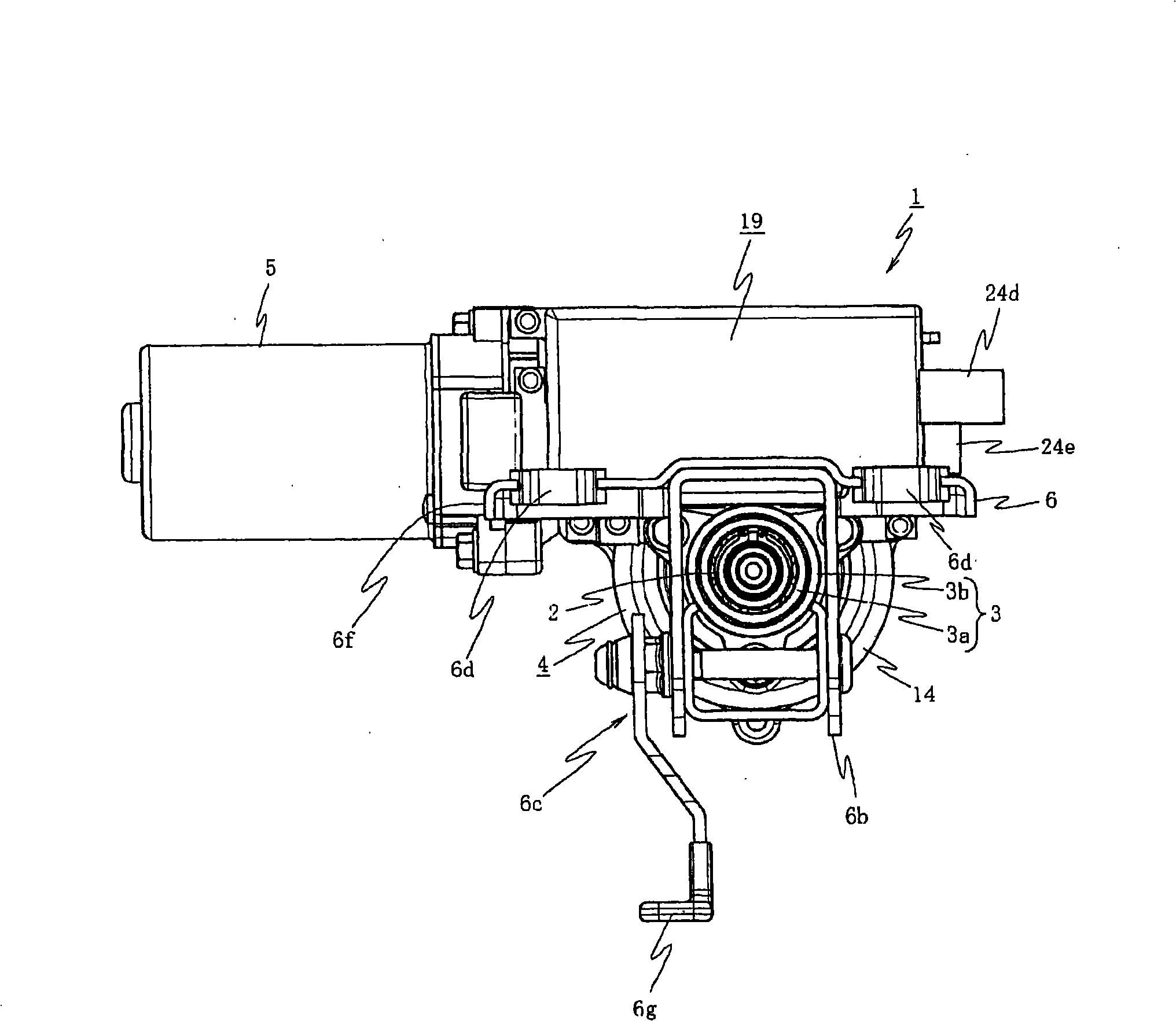
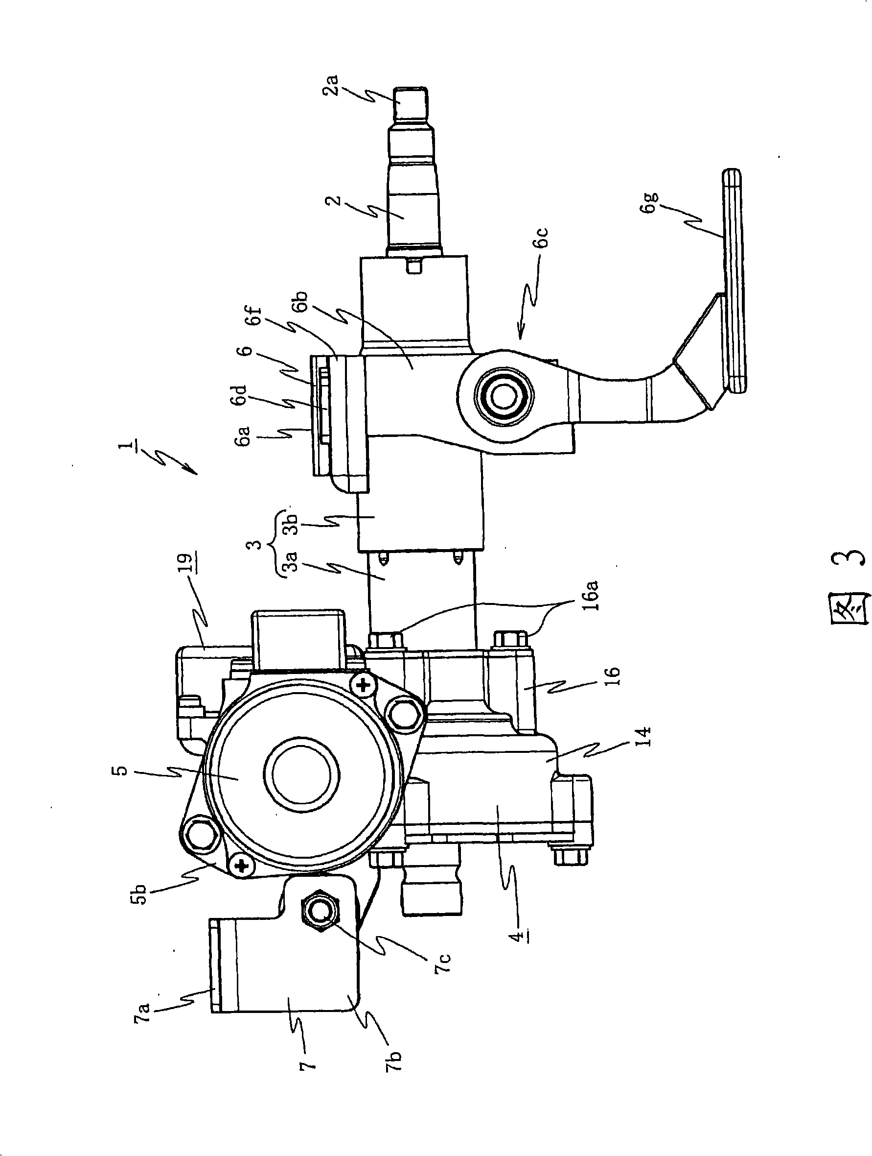
[0065] figure 1 It is a perspective view of an example when an embodiment of the present invention is applied to a right-hand steering vehicle, figure 2 is the front view, Figure 3 is the left side view, Figure 4 is a top view, Figure 5 and Figure 6 It is an exploded perspective view of the main part.

[0066] figure 1 Among them, 1 is a column type electric power steering device, a steering shaft 2 is rotatably built in a steering column 3, and the steering shaft 2 has a steering wheel assembly part 2a for assembling a steering wheel (not shown). 3 is connected to a reduction gear box 4, and an electric motor 5 constituted by a brush motor is disposed on the reduction gear box 4, and the axial direction of the electric motor 5 extends in a direction perpendicular to the axial direction of the steering column 3.

[0067] Here, the steering column 3 adopts a double-tu...


PUM


Abstract

To provide an electric power steering apparatus in which it is possible to reduce a size of the entire structure of a control unit while sufficiently showing a heat radiation effect of heat generating members. The electric power steering apparatus includes a steering column 3 having inserted therein a steering shaft 2 to which steering torque is transmitted, a reduction gear box 4 coupled to the steering shaft 2, and an electric motor 5 that transmits a steering assisting force to the steering shaft 2 via a reduction mechanism in the reduction gear box. In the reduction gear box 4, a motor mounting section 17 for mounting the electric motor 5 is formed at an end face in a direction perpendicular to an axis of the steering shaft 2 and a control-unit mounting section 20 for mounting a control unit 19 for controlling to drive the electric motor 5 is formed near the motor mounting section 17.

Description

technical field [0001] The present invention relates to an electric power steering apparatus having: a steering column in which a steering shaft to which steering torque is transmitted; and an electric motor that assists steering via a reduction mechanism in a reduction gear Force is transmitted to the steering column. Background technique [0002] As a conventional electric power steering device, for example, an electric power steering device is proposed in which a motor is accommodated in a rack case or a part of a steering gear box for accommodating or assembling a rack shaft in a slidable The housing of the control board that controls the drive of the motor is formed in the rack case or the steering gear box, and when the control board inserted through the opening abuts against a mounting boss (boss) formed at the bottom of the housing opposite to the opening When connected, the board connection terminals provided on the control board and the motor-side connection termi...

Claims


Application Information

Patent Timeline
IPC IPC(8): B62D5/04B62D1/19H02K7/116
Inventor 关根孝明大岛淳儿玉徹也小林诚一樫本圭司川田秀明篠原茂雄仙波刚
Owner NSK LTD
Learn More