
Oscillator circuit

A technology of oscillators and circuits, applied to electrical components, generating electric pulses, pulse generation, etc., can solve the problem that the operating frequency range of oscillator circuits cannot be greatly changed.

Active Publication Date: 2010-06-09
AU OPTRONICS CORP
View PDF5 Cites 0 Cited by
  • Summary
  • Abstract
  • Description
  • Claims
  • Application Information

AI Technical Summary

Problems solved by technology

However, the conditions for the oscillator to start up must be such that the loop gain must be greater than 1 in addition to the loop phase offset being an integer multiple of 360 degrees.
Therefore, in order to make the gain greater than 1, the operating frequency range of the oscillator circuit is limited and cannot be greatly changed.

Method used


Image

  • Oscillator circuit
  • Oscillator circuit
  • Oscillator circuit

Examples


Embodiment Construction

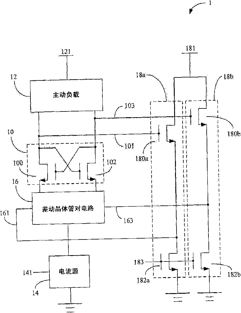
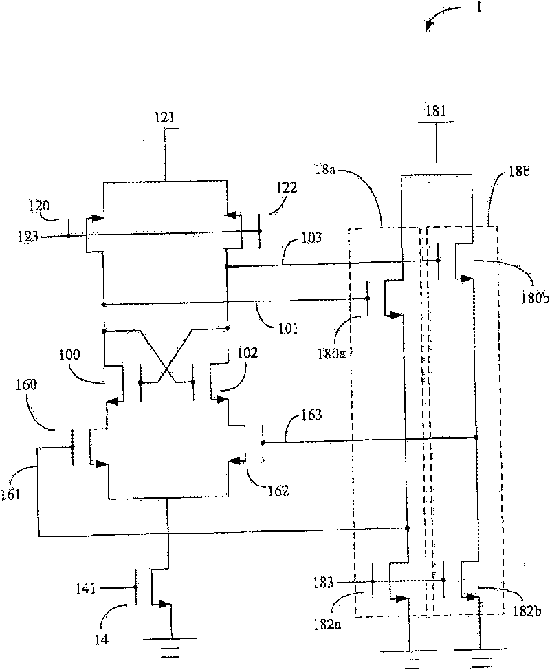
[0012] Please also refer to figure 1 and figure 2 , are respectively a block diagram of an oscillator circuit 1 and a detailed circuit diagram of the oscillator circuit 1 according to the first embodiment of the present invention. The oscillator circuit 1 includes: a cross transistor pair circuit 10, an active load circuit 12, a current source 14, a differential transistor pair circuit 16, a first source follower circuit 18a and a second source follower circuit Circuit 18b. The cross-transistor pair circuit 10 includes a first transistor 100 and a second transistor 102, the drain of the first transistor 100 is connected to the gate of the second transistor 102 and a first output 101, and the gate of the first transistor 100 is connected to To the drain of the second transistor 102 and a second output 103, there is an output voltage between the first output 101 and the second output 103; the active load circuit 12 includes two active load transistors 120 and 122, and the two...


PUM


Abstract

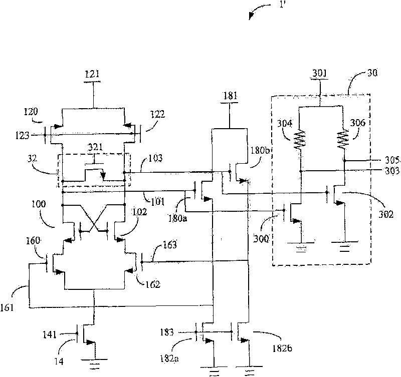
The present invention relates to an oscillator circuit, and comprises a cross transistor pair circuit, an active load circuit, a current source, a differential transistor pair circuit, a first sourceelectrode random coupling circuit, and a second source electrode random coupling circuit. The cross transistor pair circuit comprises a grid electrode and a drain electrode, which are connected with each other and are respectively provided with a first transistor with a first output and a second transistor with a second output; an output voltage is arranged between the first output and the secondoutput; the active load circuit is connected with the drain electrodes of the first transistor and the second transistor; the current source is connected with a grounding end and is coupled with a fixed voltage so as to provide current; the differential transistor pair circuit comprises a first differential input and a second differential input, and is used for connecting the source electrodes ofthe first transistor and the second transistor and the current source; the first source electrode random coupling circuit is connected with the first output and the first differential input; the second source electrode random coupling circuit is connected with the second output and the second differential input; the first source electrode random coupling circuit and the second source electrode random coupling circuit respectively comprises a load transistor which is used for receiving a modulation voltage and changing the delay time of the oscillator circuit.

Description

【Technical field】 [0001] The present invention relates to an oscillator circuit, and in particular to an oscillator circuit that changes a delay time through a modulation voltage. 【Background technique】 [0002] An oscillator circuit is a circuit with a wide range of applications. For example, the transponder module widely used in radio frequency identification (RFID) systems such as leisure cards and access control chip cards requires an oscillator circuit for sensing. The most basic oscillator circuit is composed of inductance components, but in practice, because the inductor occupies a large area, it will undoubtedly cause negative effects for the increasingly smaller integrated circuit size. [0003] The use of the Ring-type oscillator makes the area much smaller than the oscillator composed of inductive components. However, the condition for the oscillator to start oscillating is that the loop phase offset must be an integral multiple of 360 degrees, and the loop gain...

Claims


Application Information

Patent Timeline
Patent Type & Authority Patents(China)
IPC IPC(8): H03K3/0231
Inventor 游岳华陈怡然李宇轩
Owner AU OPTRONICS CORP
Learn More