
Network terminal control method and network terminal control system

A network terminal and control method technology, which is applied in the field of network terminal control methods and network terminal control systems, can solve the problems of increased management difficulty, inconvenience, coarse monitoring granularity, etc., to reduce maintenance difficulty, facilitate recording, and improve management accuracy Effect

Inactive Publication Date: 2009-01-14
NEW H3C TECH CO LTD
View PDF0 Cites 30 Cited by
  • Summary
  • Abstract
  • Description
  • Claims
  • Application Information

AI Technical Summary

Problems solved by technology

[0009] (1) Due to the need to manually set the corresponding relationship between monitoring terminals and physical locations one by one on the video application server, especially when the physical location of the monitoring terminal changes, it is also necessary to manually update, adjust and bind on the video application server, Therefore, in the case of large-scale deployment of monitoring terminals, maintenance personnel are still required to perform a lot of configuration and maintenance work, which is very inconvenient;
[0010] (2) The maintenance personnel are all based on the IP address of the monitoring terminal to implement the video application server to debug and maintain the monitoring terminal. Since the IP address is difficult to remember, and the difference between them is very small, it is easy to confuse, thus increasing the difficulty of management;
[0011] At the same time, the IP address can only be accurate to the monitoring terminal level. In the actual network environment, a monitoring terminal may manage multiple applications related to physical locations. For example, a network video encoder can manage multiple cameras. The video encoder is configured with an IP address, and although the cameras it manages monitor different physical locations, they do not have independent IP addresses themselves; this means that the monitoring granularity of the video application server for the monitoring terminal is very thick

Method used


Image

  • Network terminal control method and network terminal control system
  • Network terminal control method and network terminal control system
  • Network terminal control method and network terminal control system

Examples


Embodiment Construction

[0033] Specific embodiments of the present invention will be described in detail below. It should be noted that the embodiments described here are for illustration only, and are not intended to limit the present invention.

[0034] Based on the specification description and the consideration of easy reading, the terms appearing in the patent application documents of the present invention are defined one by one as follows:

[0035] A network terminal, also called a user agent (User Agent, referred to as UA), mainly refers to a terminal related to a physical location in the network in the present invention, such as a video encoder;

[0036] Device Identifier (DEV-ID for short): an identifier that uniquely identifies a device, which can be a binary string or a string;

[0037] Device Application Identifier (DEV-APP-ID for short): an identifier that uniquely identifies a device application within a device; it should be noted that the above terms are only used as one of the names ...


PUM


Abstract

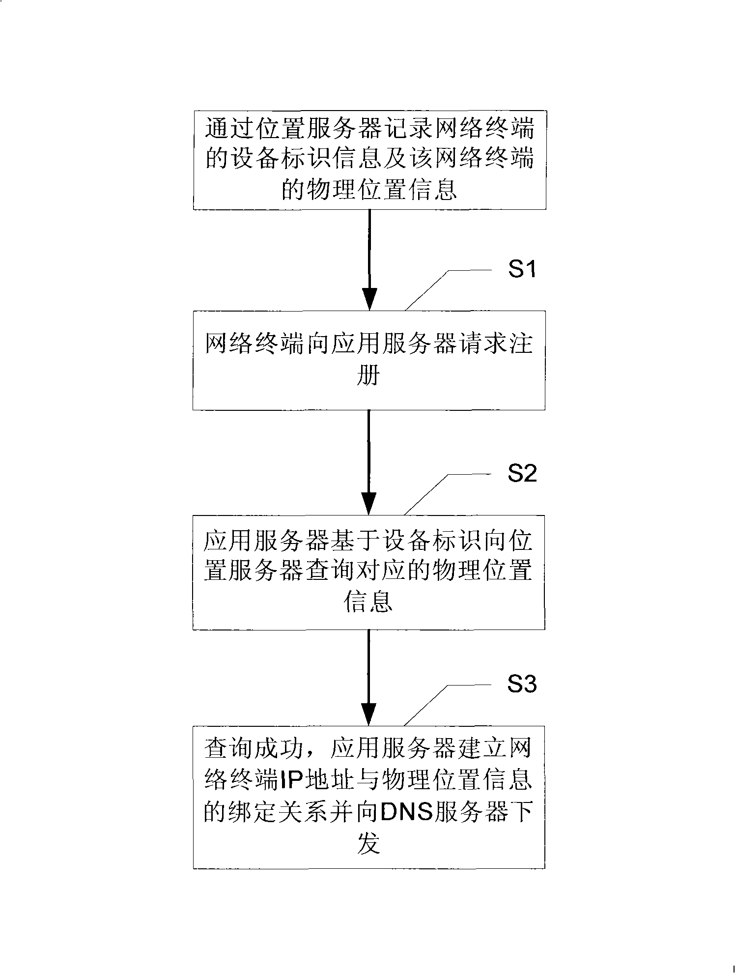
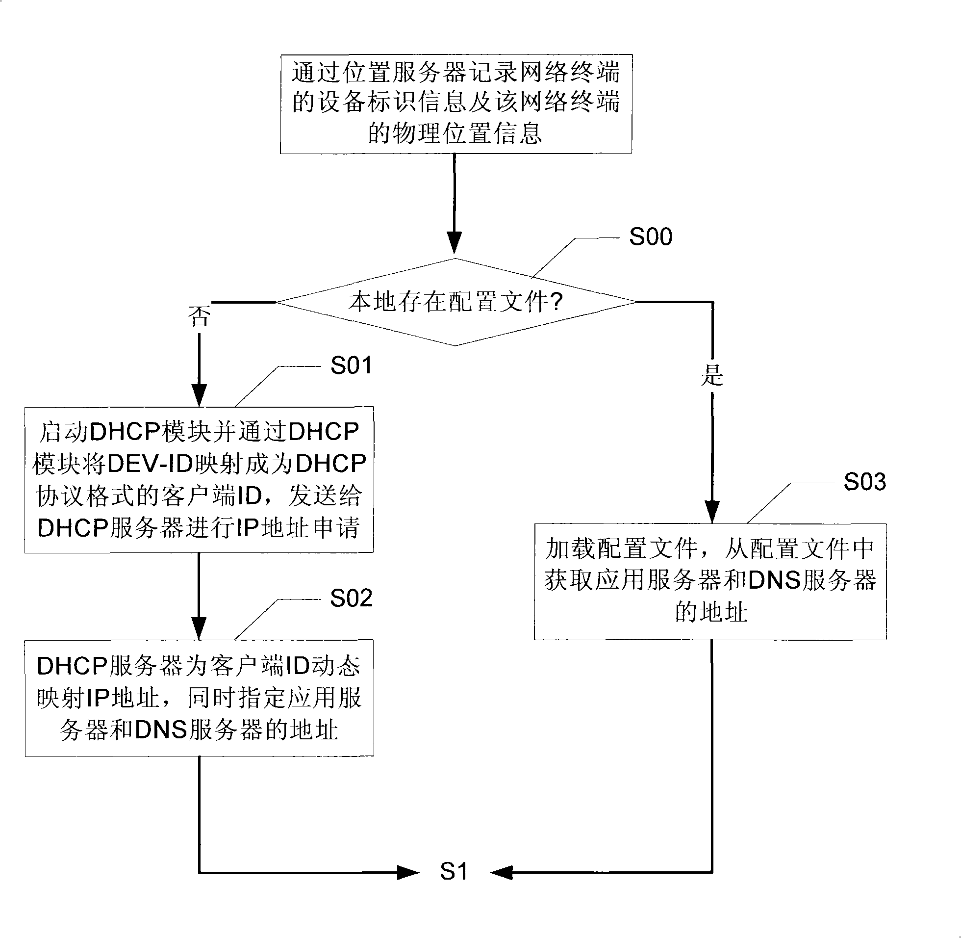
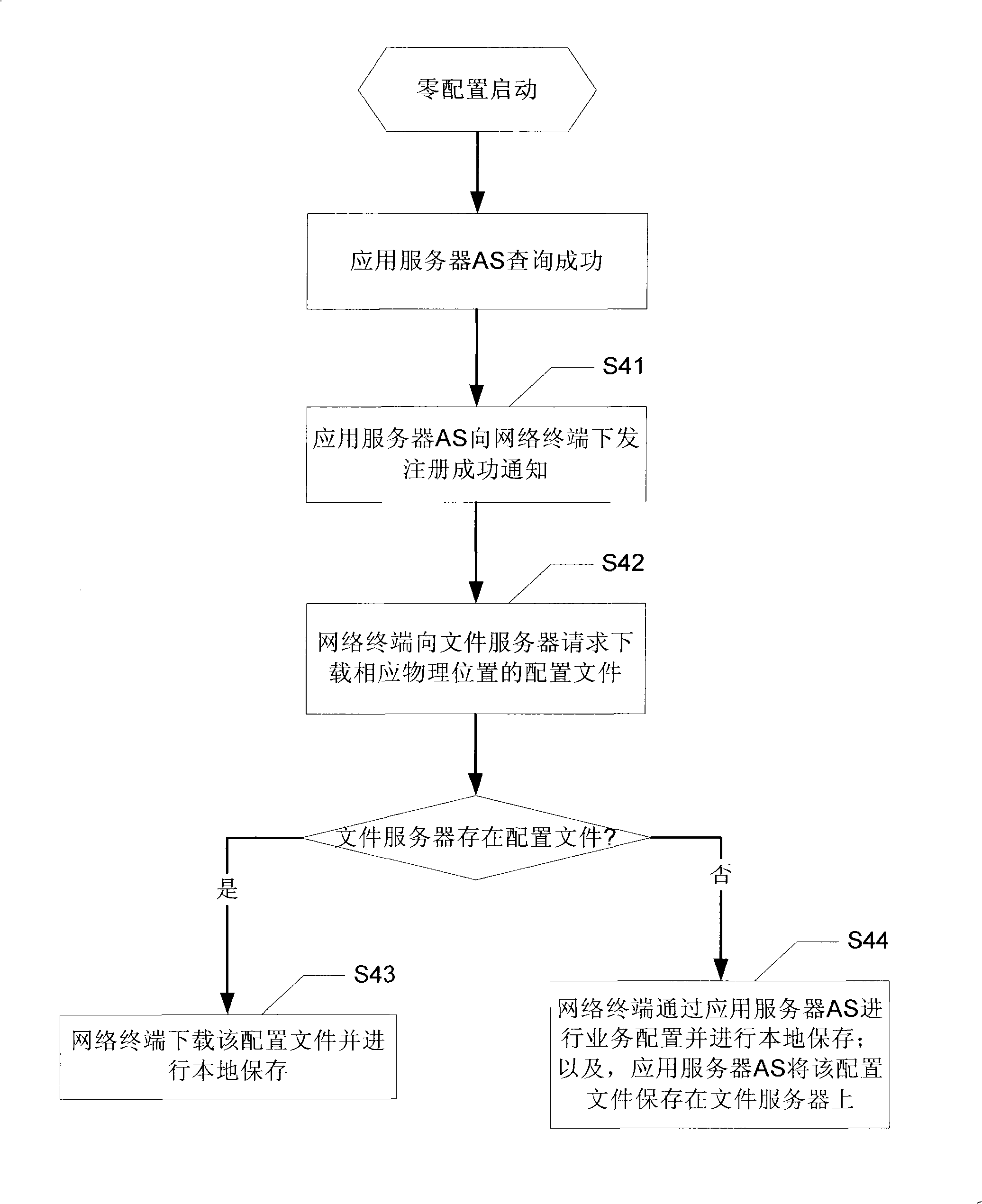
The invention discloses a network terminal control method and a network terminal control system, comprising: recording device identification information of the network terminal and physical position information of the network terminal through a position server, and executing the steps after starting a network terminal: the network terminal request to register to an applying server, wherein the registering information is carried with ID address of the network terminal and the device identification information; the applying server inquires the physical position information corresponding to the network terminal to the position server based on the physical position information; if true, the applying server builds binding relation between the IP address of the network terminal and the physical position information and sends down to a DNS server, to perform visit on the network terminal based on the physical position information. According to the invention, it is in favor of disposition of larger network, thereby effectively reducing maintaining difficulty of the network terminal.

Description

technical field [0001] The invention relates to the technical field of network communication, in particular to a network terminal control method and a network terminal control system. Background technique [0002] With the continuous development and popularization of network technology, the number of terminals in the operator's or enterprise LAN has increased dramatically. Due to the scattered physical locations of network terminals, it is expensive to configure and maintain them separately. Therefore, in the prior art, application servers are often used to centrally manage the terminals in the network, so that network configuration, maintenance and upgrade The workload is concentrated on the application server to greatly reduce the workload of maintenance personnel. [0003] However, in the prior art, the management of the network terminal by the application server is generally based on the IP address of the network terminal. For some network terminals that are highly corr...

Claims


Application Information

Patent Timeline
Patent Type & Authority Applications(China)
IPC IPC(8): H04L12/24H04L29/06H04L29/12
Inventor 宁军刘靖非
Owner NEW H3C TECH CO LTD
Learn More