
Permanent magnet motor with shaft radial folding winding

A permanent magnet motor, shaft radial technology, applied in the shape/style/structure of the winding conductor, the magnetic circuit characterized by magnetic materials, and the static parts of the magnetic circuit, etc., can solve the problem that the torque density and Power density, small effective utilization of permanent magnet motor space, and non-compact motor structure, to achieve the effect of improving overall operating efficiency, compact motor structure, high motor power density and torque density

Active Publication Date: 2011-07-20
日照菁英传媒科技有限公司
View PDF0 Cites 0 Cited by
  • Summary
  • Abstract
  • Description
  • Claims
  • Application Information

AI Technical Summary

Problems solved by technology

[0005] The purpose of the present invention is to solve the problem that the current permanent magnet motor has a small effective space utilization rate, the motor structure is not compact, and the torque density and power density cannot be effectively improved, and a permanent magnet motor with axial and radial folded windings is designed.

Method used


Image

  • Permanent magnet motor with shaft radial folding winding
  • Permanent magnet motor with shaft radial folding winding
  • Permanent magnet motor with shaft radial folding winding

Examples


specific Embodiment approach 1

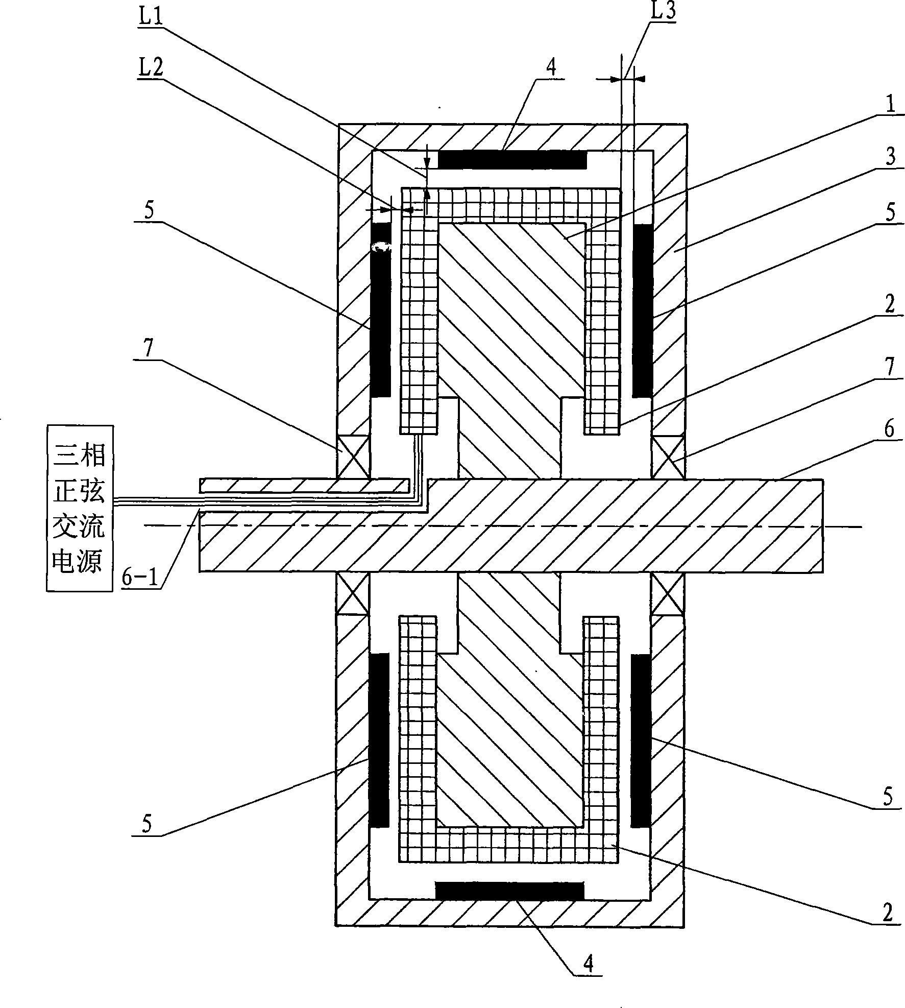
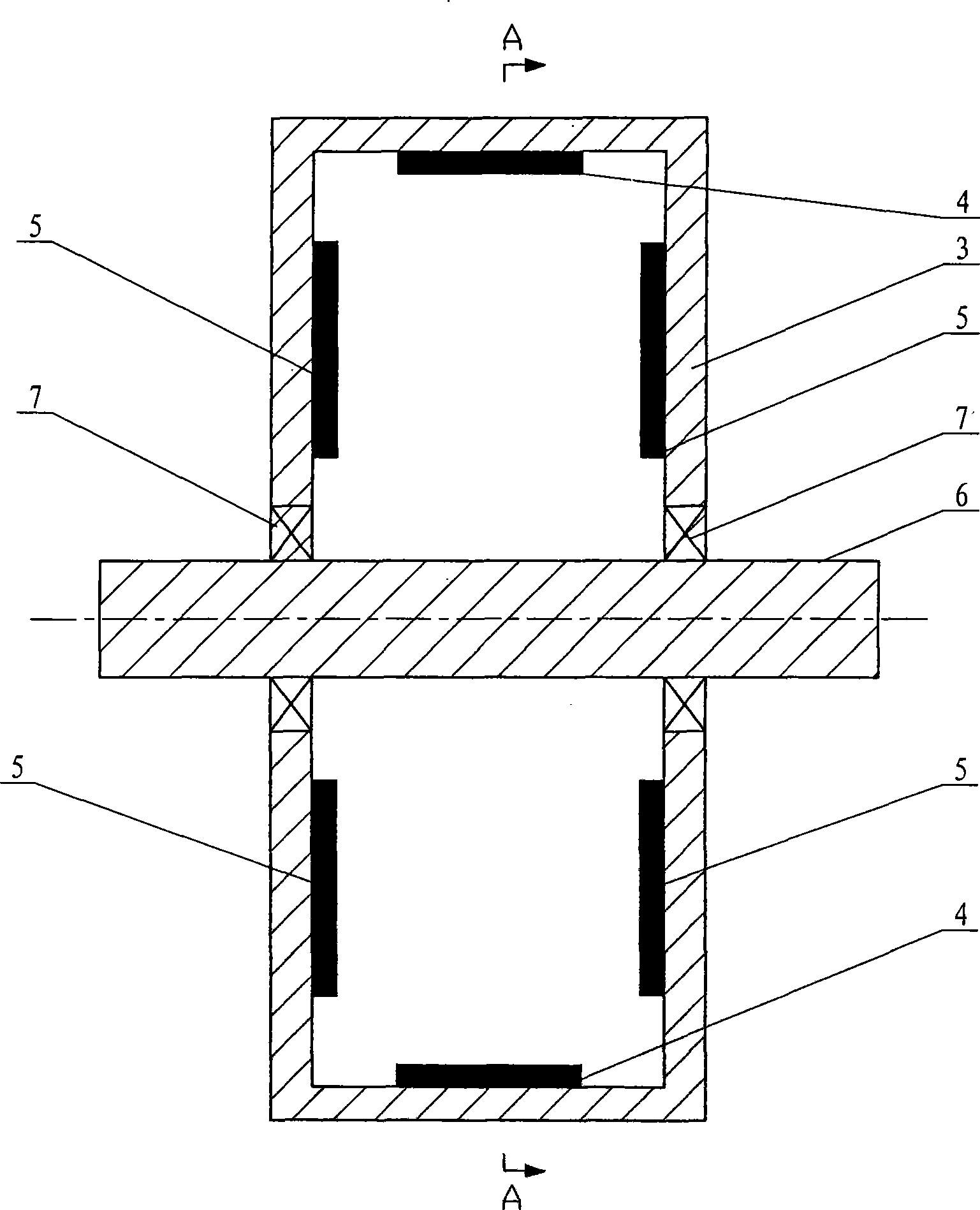
[0012] Specific implementation mode one: the following combination Figure 1 to Figure 5 Describe this embodiment, this embodiment is made up of stator, rotor and shaft 6, and stator is fixed on shaft 6, and rotor is arranged on the outside of stator, and described stator is made up of stator core 1 and stator winding 2, and stator core 1 is Ring, the outer surface of the stator core 1 is provided with a plurality of axial slots 1-1, the opening centerline of the axial slots 1-1 is axial, and the plurality of axial slots 1-1 surround the shaft 6 Evenly arranged, the two sides of the stator core 1 are respectively provided with a plurality of radial slots 1-2, and the opening centerlines of the plurality of radial slots 1-2 are evenly arranged radially around the shaft 6, and the axial slots 1 -1 corresponds to the radial slots 1-2 on both sides of the stator core 1 respectively, and communicates with each other respectively. The stator winding 2 is arranged in the -2, and the...


PUM


Abstract

The invention discloses a permanent magnet motor with axial radial folding winding belonging to the motor field. The object of the invention is to solve the problems that the space effective utilization rate of the permanent magnet motor is low and the motor structure is not compact, thereby the torque density and power density are not effectively improved. The permanent magnet motor comprises a stator, a rotor and a shaft, wherein the stator is fixed on the shaft, the rotor arranged exterior of the stator rotationally connects with the shaft, a plurality of axial slots are uniformly distributed on the cylindrical surface of the round stator core, a plurality of radial slots are uniformly distributed in a radial form on the end faces of the two sides of the stator core, the axial slots and the radial slots are one-to-one correspondence and respectively communicate. A stator winding is arranged together on each axial slot and corresponding radial slot, a plurality of first permanent magnets are uniformly distributed on the inner circle wall of the rotor core and uniformly arranged around the shaft. A plurality of second permanent magnets are uniformly distributed in a radial form on the inner surface on each end face of the two sides of the rotor core, and the stator winding is a multiphase symmetric winding.

Description

technical field [0001] The invention belongs to the field of motors. Background technique [0002] At present, the commonly used permanent magnet motors include radial flux cylindrical permanent magnet motors and axial flux disc permanent magnet motors. They have a common problem that the effective utilization of motor space is small, and the motor structure is not compact. Effectively improve torque density and power density. [0003] For the radial flux cylindrical permanent magnet motor, when the length of the motor is relatively small, the influence of the length of the end of the winding is relatively large. When the radius of the motor is large, the ratio of the length of the end of the winding at both ends of the motor to the total length of the motor is relatively large. It is very large, which wastes copper wire and increases copper loss; and a large part of the space between the bottom of the slot and the shaft is not used; on the other hand, the axial length of t...

Claims


Application Information

Patent Timeline
Patent Type & Authority Patents(China)
IPC IPC(8): H02K1/16H02K3/12H02K1/27H02K1/02
Inventor 郑萍沈琳孙红超罗昌德
Owner 日照菁英传媒科技有限公司
Learn More